Use this dialog to define the parameters of an RC column.
Access
- Click Design
 Required Reinforcement of Beams/Columns - Options Code parameters to open the R/C Member Type dialog, and then click
  .
. - Click
 (R/C Member Type) to open the R/C Member Type dialog, and then click .
Dialog elements
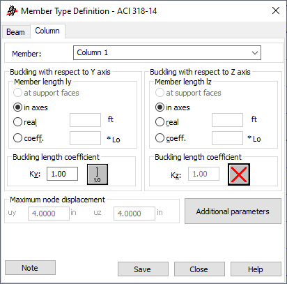
- Member
- Displays the name of the selected member type. The default name is: "Column" and is assigned the first number available. You can also enter another name in place of the default.
- Buckling with respect to Y and Z axis
-
- The Member length Iy and Iz contain options that define the calculation length of a column. There are four ways to define the length:
- Click At support faces. The distance between the faces of the top and bottom supports of a column is adopted as a design length.
- Click In axes option. The design length equals the actual column length .
- Click Real option, and enter the length .
- Click Coefficient, and enter a value. The value becomes the coefficient by which the length at support faces should be multiplied to obtain the required value. For example, if you enter a value of 0.25, it means that the required value equals ¼ of the length at support faces. L 0 denotes the column length between the nodes.
- The Buckling length coefficient field defines the buckling length coefficients for a member in both directions.
The buckling length coefficient depends on the support conditions of the end nodes of a member in the buckling plane. The buckling length of a member may also be determined by clicking the icon that displays schematically the selected buckling model of a member in the Buckling schemes dialog. The dialog contains typical schemes of member support conditions. After a scheme is selected, the value of the coefficient will be adopted or calculated automatically.
Buckling applies when a compression force affects a member, even if it is small when compared to other internal forces. Robot does not check, if you can ignore or not buckling effects in calculations. If you want to eliminate buckling effects from calculations, select the last icon from among those located in the Buckling schemes dialog. If the icon is selected, buckling will be disregarded in calculations.
- The Member length Iy and Iz contain options that define the calculation length of a column. There are four ways to define the length:
- Maximum node displacement
- Defines the maximum relative displacements of column nodes in directions Y and Z. If the displacements are exceeded, the table of calculation results displays an appropriate warning.
- Additional parameters - available for some RC codes. Click it to open a dialog for defining additional parameters.
- Note - click it to display a calculation note.
- Save - click it to add a member type with the defined name and parameters to the list of the formerly-defined RC member types.
Use the buttons at the bottom to: