To control the angular dimensions of a family, apply a labelled angular dimension to a reference line.
Unlike reference planes (with infinite extents), a reference line has specific start and end points and can be used to control the angular constraints within components such as a web truss, a door with an instance door swing, or an elbow.
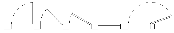
Loaded door family with an angular dimensioned reference line
 Video: rotate Family Geometry with an Angular Parameter
To add and dimension a reference line
- In the drawing area (while in the Family Editor), add a reference line with the point of origin located at the point of expected rotation and align and lock the endpoint.
- Add an angular dimension referring to the reference line.
- Label the dimension.
- On the Properties palette, click
 (Edit Type).
- In the Family Types dialog, change the angular value for the labelled dimension, and click Apply.
This is known as flexing the model. It is important to make sure the reference line adjusts as expected before adding model geometry to it.
To add and align model geometry to a reference line
- Set the current work plane to one of the faces of the reference line.
- Add the model geometry that you intend to have controlled by the angular dimension.
- Flex the model to make sure the design works as expected.
The geometry moves with the reference line as the angle changes.