When elements are transparent, only edges and fill patterns (including solid fills) are drawn on element faces.
Note: If you need to apply transparency to an individual model element face, see
Override Visibility and Graphic Display of Individual Elements.
- Open the view in which you want to apply transparency to model category faces.
- Click View tab
 Graphics panel
 (Visibility/Graphics), or right-click an element in the drawing area, and click Override Graphics in ViewBy Category.
- In the Visibility/Graphics dialog, click the Model Categories tab.
If you are editing model categories for elements in a linked model
- Click the Revit Links tab.
- Click the button in the Display Settings column.
- In the RVT Link Display Settings dialog, click Custom.
- Click the Model Categories tab.
- Select <Custom> from the drop-down menu.
- Highlight a category row or rows.
- In the Transparent column, select the check box.
- Click Apply to view your changes, and click OK to exit the Visibility/Graphics dialog.
When elements are transparent, only edges and fill patterns (including solid fills) are drawn on element faces. The faces between pattern lines are not drawn. In Hidden Line view and Shaded view, parts of edges are hidden. An edge can be hidden by the face of any non-transparent element, and by a face of its own element (even when it is marked transparent). Edges are not hidden by other transparent elements.
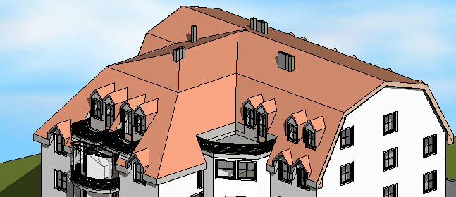
Example
The following images show the same model in 3D view. The second image shows how part of the roof looks when transparency is applied.