Create braces by sketching a line between two structural elements. For example, braces can appear between a structural column and a structural beam.
You can add braces in either a plan view or in a framing elevation view.
To add a brace in a framing elevation view
- Open a framing elevation view.
- If necessary, load additional braces from the Structural/Framing folder under the Library folder of the Revit program group.
- Click Structure tab
 Structure panel
 Brace.
 - On the Properties palette, select the appropriate brace from the Type Selector drop-down.
- To edit the properties of the brace before adding the brace to your model, click on the Properties palette.
- In the drawing area, highlight the snapping point where you want to begin the brace, such as on a structural column. Click to place a start point.
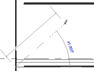
Snap to begin brace
- Move the pointer in a diagonal direction to sketch the brace and place the cursor near another structural element to snap it. Click to place the endpoint.
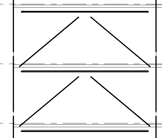
Sample braces in a framing elevation view
To add a brace in a plan view
- Open a plan view.
- Click Structure tabStructure panel Brace.
- On the Options Bar, specify both the Start Level and offset distance and the End Level and offset distance.
- Click the start point and the endpoint of the brace in the project.