Projects created prior to Autodesk Revit 2014 will need a manual upgrade of steel beam families to fully remove legacy parameters and their behaviors.
 Video: Upgrade Steel Framing Families in Legacy Projects
This procedure shows you how to upgrade steel beam families to remove old extension parameters and fully utilize new geometric positioning behaviors.
This particular example uses the W-Wide Flange.rfa family, but all beams and braces in the project should be upgraded.
- Open the family to be updated in the Family Editor.
- Open a Ref. Level view of the family.
- In the Properties palette, verify the Material for Model Behavior parameter is Steel (or any family created with a non-cast-in-place concrete template such as Wood, Light Gauge Steel, or Precast Concrete). If not, the family should not be updated.
- Click Modify tab
 Properties panel
 (Family Types).
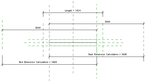
- In the Family Type dialog, verify the following parameters are present:
- under Construction, Start Extension
- under Construction, End Extension
- under Other, Start Extension Calculation with a formula containing Start Extension
- under Other, End Extension Calculation with a formula containing End Extension.

If these conditions are not fulfilled, the family should not be updated.
- Select each of the four parameters listed in the previous step and click Remove. Once all four are removed, click OK to close the Family type dialog.
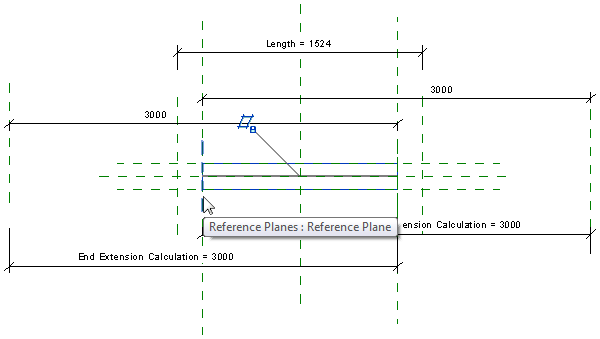
- In the Ref. Level view, select the unnamed reference plane immediately to the left of the sweep and press
Delete. Note that another reference line is immediately below the deleted reference. Leave that in place.
- Repeat the process in step 7 to delete the reference line to the right of the sweep.

- Select the sweep.
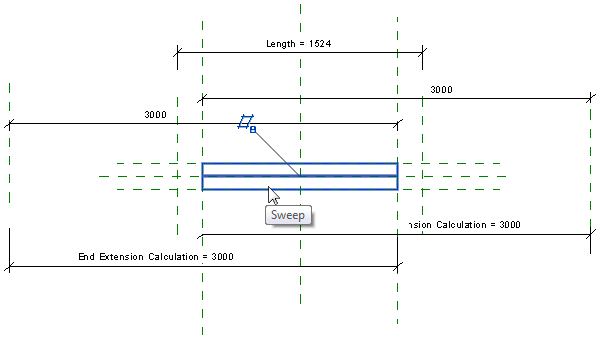
- Click Modify | Sweep tabMode panel
 (Edit Sweep).
- Click Modify | Sweep tabSweep panel
 (Sketch Path).
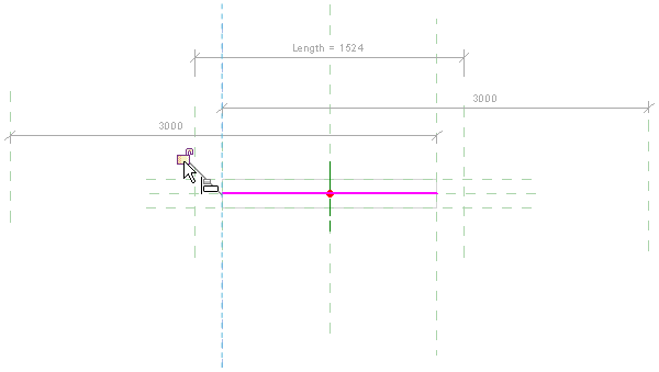
- Select the path.
- Click Modify | Sweep > Sketch Path tabModify panel
 (Align).
- Select the Member Left reference plane.

- Select the left side of the path.
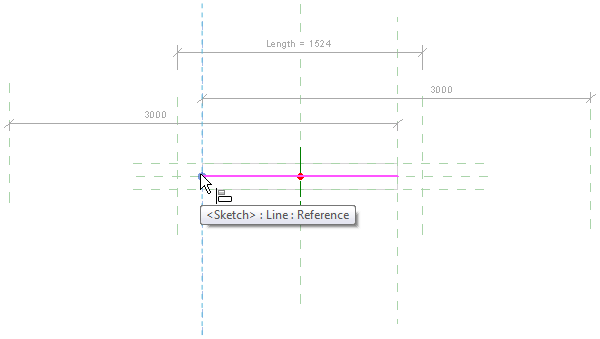
- Lock this alignment.
- Repeat steps 14 - 16 using the Member Right reference plane and the right side of the path.
- Click Modify | Sweep > Sketch Path tabMode panel
 (Finish Edit Mode).
- Click Modify | Sweep tab Mode panel (Finish Edit Mode).
- On the View Control Bar, click
 (Temporary Hide/Isolate) Hide element. The Medium detail level sweep is now hidden; the fine detail level sweep is now exposed.
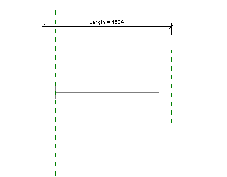
- Repeat steps 9 - 19 to adjust the constraints for the Fine detail sweep.
- On the View Control Bar, click
(Temporary Hide/Isolate) Hide element. The Fine detail level sweep is now hidden; the two symbolic lines representing the web of the steel element is now exposed. You may need to zoom in to see them distinctly.
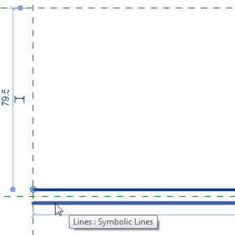
- Click Modify tabModify panel (Align).
- Repeat steps 14 - 17 to adjust the constraints for both symbolic lines.
- On the View Control Bar, click
(Temporary Hide/Isolate) Reset Temporary Hide/Isolate to restore all hidden elements.
- Select the unnamed reference plane to the far left and press Delete.
- Select the unnamed reference plane to the far right and press
Delete. The family is now updated.
- Save the family. When reloaded into a project, the family will no longer possess the Start and End Extension parameters, Start and End Extension Calculation parameters, or shape handles for editing extensions.