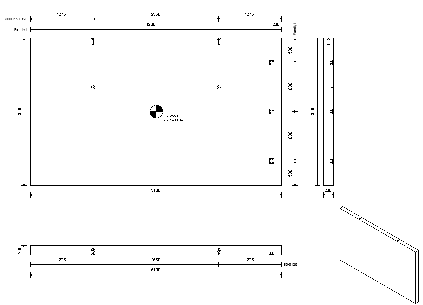
Review different workflow examples of dimensioning mounting parts in precast shop drawing views.
Dimensioning Mounting Parts on One Dimension Line
The dimensions of all mounting parts of the same family will be placed on one line, if the mounting parts are placed on the same side of the host. The reference for this placement is the center of the element. All mounting parts with the same family name that are on top of the center of the host will be dimensioned on top of the element. The mounting parts below the center will be dimensioned below the element. The same rule applies for vertical dimension lines. Dimension points on the extents of the host are added to the dimension line, besides the dimension points of the mounting parts (one point left & right or top & bottom).
Example: Dimension the center of the anchor plates in both directions, in a top view
- Open the anchor plate family, from: Libraries\US Metric\Structural Connections\Mounting Parts\Fastening Plates\M_Plate with Anchors.rfa
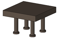
- In the Project Browser, switch to the Floor Plans, Ref. Level and create one horizontal model line and one vertical model line, intersecting in the center of the anchor plate.
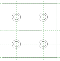
- Define the "Dimension_Top" subcategory and set it as the subcategory for the two lines.
- Define the Visibility dimension line instance parameter and set the lines to invisible.
- Load the anchor plate family into a project and place it on a wall.
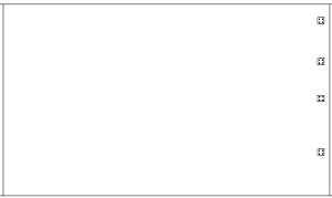
- Click Precast tab
 Segmentation panel
 (Split) to split the wall.
- Click Precast tab
 Connections panel
 (Mounting Parts) to add the anchor plates into the assembly.
- Click Precast tab
 Fabrication panel
 (Shop Drawings) to create a shop drawing for the assembly.
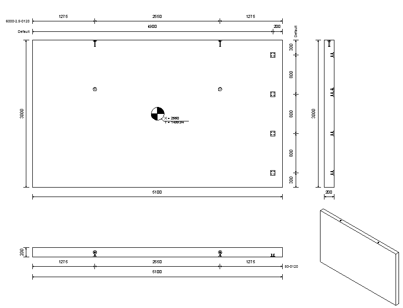
Based on the name of the subcategory, the dimension lines should be created only when viewing the anchor plates from the top (as seen in the family). For the wall in this example that is only in the frontal view.
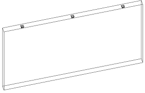
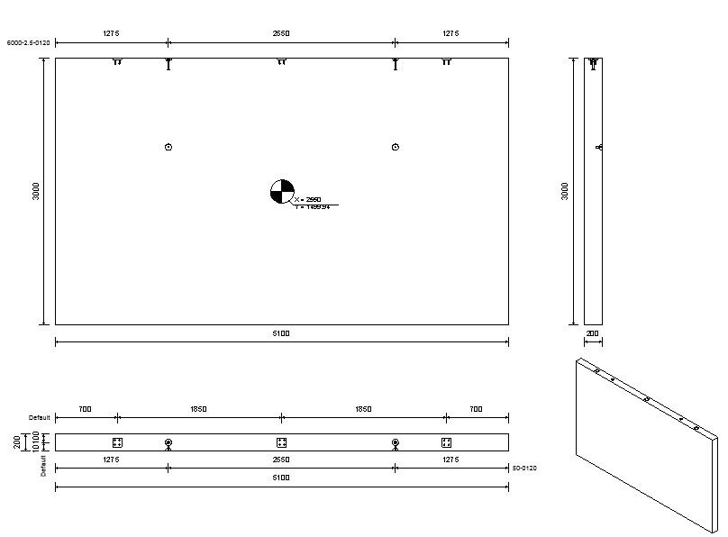
Example: Dimension the anchor plate family using only one dimension line
- Create only one dimension line, instead of two lines intersecting in the center. Place the line in the center of the family, orthogonal to the plane of the anchor plate.
-
Set a subcategory and the visibility parameter as in the first example.
- Load the family into a project and place it on a wall.
- Click Precast tab
 Segmentation panel
 (Split) to split the wall.
- Click Precast tab
 Connections panel
 (Mounting Parts) to add the anchor plates into the assembly.
- Click Precast tab
 Fabrication panel
 (Shop Drawings) to create a shop drawing for the assembly.
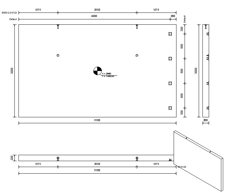
- In the first example it would have been possible to create only one line as presented above, getting dimensions only vertically or only horizontally; in the second example both directions are dimensioned using the same reference line.
- If the anchor plate is added rotated in the first example, it cannot be dimensioned at all (reference lines are no longer parallel to the axis of the wall); in the second example the center of the plate is always dimensioned.
Example: Dimension the anchor plate using the contour of the family
- Remove any dimension lines from the family.
- Load the family into the project.
- Click Precast tab
 Fabrication panel
 (Shop Drawings) to create a shop drawing for the assembly.
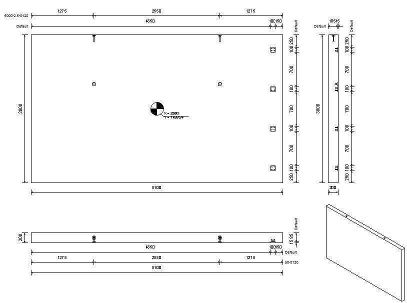
The extents of the anchor plates are dimensioned in all views (using one dimension, since it is always the same family).
In top and front views, only the plate is dimensioned (without the anchors), because in these views only the round faces of the anchors are visible, thus giving no references to dimension.
Example: Dimension using nested families
- Create a new family, using the Metric Generic Model face based template.
- Load the anchor plates with dimensioning into the family and place three instances on the top face o f the family body.
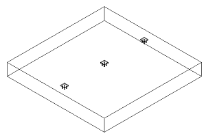
- Place the new family on the wall.
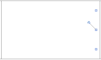
- Click Precast tab
 Segmentation panel
 (Split) to split the wall.
- Click Precast tab
 Fabrication panel
 (Shop Drawings) to create a shop drawing for the assembly.
