Connection Library AISC Steel Construction Manual
This connection library is based on the AISC Steel Construction Manual. There are two sets of library files: one based on the 14th edition and the other based on the 15th edition.
This connection library content depends on the US imperial structural steel profiles, it is intended to be used in projects based on this content. You need to download and install the US imperial content first. Download and install country-specific content.
Note: The delivered library files are practice examples about how national standards can be used to enable an automatic placement of simple steel connections, using ranges of applicability and Dynamo scripts. They can serve as a starting point for building your own company standards.
Considering that we did not implement all the detailed specifications included in this manual and in the other relevant standards linked to it, each connection library is built based on specific geometric assumptions for the connection configuration. You can extend the library files based on your specific requirements.
Connection library content
The provided connection library consists of 13 library files containing a total of 726 Revit connection types with attached ranges of applicability defined based on the AISC Steel Construction Manual.
- “AISC 10.1BB.rvt” – based on AISC manual Table 10-1 – “All-bolted Double-Angle connections”.
- “AISC 10.2BW.rvt” – based on AISC Manual Table 10-2 – “Available Weld Strength of Bolted/Welded Double-Angle Connections”.
- “AISC 10.2WB.rvt” – based on AISC Manual Table 10-2 – “Available Weld Strength of Bolted/Welded Double-Angle Connections”.
- “AISC 10.3WW.rvt” – based on AISC Manual Table 10-3 – “Available Weld Strength of All-Welded Double Angle Connections”.
- “AISC 10.4EP.rvt” – based on AISC Manual Table 10-4 – “Bolted/Welded Shear End-Plate Connections”.
- “AISC 10.5.rvt” – based on AISC Manual Table 10-5 – “All Bolted Unstiffened Seated Connections”.
- “AISC 10.6.rvt” – based on AISC Manual Table 10-6 – “All Welded Unstiffened Seated Connections”.
- “AISC 10.8.rvt” – based on AISC Manual Table 10-8 – “Bolted/Welded Stiffened Seated Connections”.
- “AISC 10.10A SP.rvt” – based on AISC Manual Table 10-10a – “Single Plate Connections”.
- “AISC 10.11BB.rvt” – based on AISC Manual Table 10-11 – “All-Bolted Single-Angle Connections”.
- “AISC 10.12BW.rvt” – based on AISC Manual Table 10-12 – “Bolted/Welded Single-Angle Connections”.
- “AISC 10.12WB.rvt” – based on AISC Manual Table 10-12 – “Bolted/Welded Single-Angle Connections”.
- “AISC 14.3.rvt” – based on AISC Manual Table 14-3 – “Typical Column Splices”.
Connection type names
The naming convention for defining the connection types is detailed here. This convention is especially useful for the connection types that connect to the Flange or to the Web in order to differentiate between them.
The first part of the connection type name describes the category of connected elements:
- “B to B” – beam to beam connection
- “B to C” – beam to column connection
- “C to C” – column to column connection
After the category of connected elements, for some connections the relative position of the supported element to the flange or to the web of the supporting element is specified. It can be either “Flange” or “Web”.
Next, the connection method is specified, the supporting element is first and the supported element is second:
- “BB” – both angle legs bolted
- “BW” – angle leg bolted to supporting and angle leg welded to supported beam
- “WB” – angle leg welded to supporting and angle leg bolted to supported beam
- “WW” – both angle legs welded
After this, there is information about the bolts, their diameter, grade, and the number of bolt rows. For example:
- “3/4” –
3/4"diameter bolts - “A325” – group A 325 bolts
- “4No” – 4 rows of bolts
Only for the “AISC 10.8.rvt” file, Bolted/Welded Stiffened Seated Connections, there is information about the width and length of the seat. For example “4inW 10inL” means 4 inches width and 10 inches length.
There is information about the angle profile or the plate of the connection, as the case may be. For example:
- “3/8L” –
3/8"angle profile thickness for a clip angle connection - “5/8PL” –
5/8"plate thickness for a splice joint connection
Next is the weld thickness, where applicable. For example “5/16W” means 5/16" weld thickness.
Only for the column splice connections there is additional information about the range of column sections. For example “W14X145 to W14X233”.
At the end of the connection type names there is a short code indicating the type of connection. These are:
- “CSP” – column splice (2 elements connection)
- “SCA” – single clip angle (2 elements connection)
- “SCASS” – single clip angle single side of the beam (2 elements connection)
- “DCA” – double clip angle (3 elements connection)
- “DCASS” – double clip angle single side of the beam (3 elements connection)
- “SEP” – single end plate (2 elements connection)
- “DEP” – double end plate (3 elements connection)
Here are a couple of examples and how to read them:
- “B to C Flange BW 3/4 A325 9No 3/8L 5/16W SCA” – beam to column, the beam connects to the column on the column flange, bolted to the column and welded to the beam, 3/4" A 325 bolts, with 9 rows of bolts, 3/8" angle thickness, 5/16" weld thickness on supported beam, single clip angle connection.
- “C to C Flange BB 3/4 A325 5/8PL W14X257 to W14X426 CSP” – column to column, the bolts are on the columns' flanges, bolted to both columns, 3/4" A 325 bolts, 5/8" plate thickness, column sections from W14X257 up to W14X426, column splice connection.
Example: Ranges of applicability based on the standard
This example shows a couple of connection types and how the ranges of applicability were calculated, including the internal forces. This example is based on the AISC 14th edition, chosen for illustrative purposes.
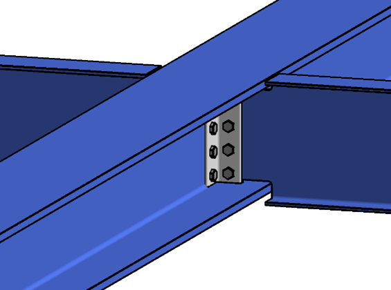
Let's look at the “B to B Web BB 3/4 A325 4No 3/8L SCA” connection type in the “AISC Connections V14\AISC 10.1BB.rvt” library file. This is a beam to beam, bolted on both legs, 4 rows of bolts with 3/4" diameter, 3/8" angle thickness, single clip angle connection. Because this is an all bolted connection we only need to look at one table in the standard:
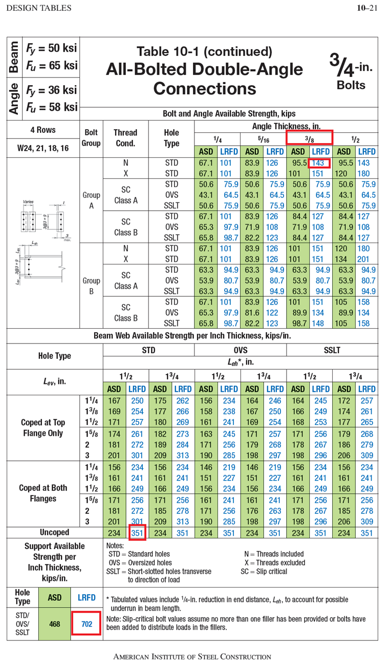
According to AISC table 10-1, the following conditions can be implemented in the ranges of applicability:
- Fz: ± 143 kips - The maximum shear force for the supported beam.
- 143 kips / 351 kips/in = 0.407 in - The minimum web thickness of the supported uncoped beam.
- 143 kips / 702 kips/in = 0.204 in - The minimum web thickness of the supporting beam.
The 14th edition of the standard specifies a supported beam web thickness of 0.407 in or greater - in our example case 1. In order to cover situations for thinner profiles the shear force can be calculated considering the thinner web thickness of the beam. This means we ca define 3 additional cases (2, 3, 4) for the ranges of applicability:
- Supported beam with a shear capacity above the bolt strength and the angle strength, meaning all the beams with a web thickness greater than 0.407 in.
- Supported beam with 3/8" web thickness, the shear capacity of the connection will be adjusted to the maximum shear strength of the supported beam: Fz = 3/8 in x 351 kips/in = 131.625 kips.
- Supported beam with 5/16" web thickness, the shear capacity of the connection will be adjusted to the maximum shear strength of the supported beam: Fz = 5/16 in x 351 kips/in = 109.687 kips.
- Supported beam with 1/4" web thickness, the shear capacity of the connection will be adjusted to the maximum shear strength of the supported beam: Fz = 1/4 in x 351 kips/in = 87.75 kips.
“Element 1”, which is the supporting beam, has no shear force condition. The web thickness resulted from the calculation above is at least 13/64 in, considering a tolerance of 1/64 in.
It is good to have a condition for the minimum height parameter of the supporting beam, because it depends on the smallest profile of the supported beam and the standard encroachment limitation.
The supported beams are the ones between W16X26 and W24X370. The smallest profile is W16X26 and it has a minimum supported beam height of 15 3/4". Calculating the supporting beam minimum height we get 3 x 3" (bolt distance between rows) + 2 x 1" (rolled edge distance) + 3 5/8" = 1' 2 5/8" = 14 5/8". Looking through table 1-1 for W-Shapes we see that the smallest profile for the supporting beam is W14X132.
“Element 2”, which is the supported beam, has the following ranges:
- First case:
- We selected all the section names for profiles with a web thickness greater than 0.407".
- Maximum Fz = ± 143 kips
- Second case:
- We selected all the section names for profiles with a web thickness equal to 3/8".
- Maximum Fz = ± 131.62 kips
- Third case:
- We selected all the section names for profiles with a web thickness equal to 5/16".
- Maximum Fz = ± 109.687 kips
- Fourth case:
- We selected all the section names for profiles with a web thickness equal to 1/4".
- Maximum Fz = ± 87.75 kips
Looking at another example, this time from the “AISC Connections V14\AISC 10.2BW.rvt” library file the “B to B Web BW 3/4 A325 4No 3/8L 5/16W SCA” connection type. This is a beam to beam, bolted to the supporting beam and welded to the supported beam, with 4 rows of bolts with 3/4" diameter, 3/8" angle thickness, 5/16" weld thickness, single clip angle connection. Because this is both a bolted and a welded connection we need to look at two tables, table 10-1 for the bolted part, and table 10-2 bot the welded part.

According to the above mentioned tables, the following conditions can be implemented in the ranges of applicability:
- The shear force capacity for welds on maximum Fz = ± 143, taking the minimum of:
- ± 143 kips, according to table 10-1
- ± 237 kips, according to table 10-2
- The minimum web thickness of the supported beam for 5/16 in welds “A” is 0.476 in. Welds “A” means the weld is connecting the angle to the supported beam, according to table 10-2.
- The minimum web thickness of the supporting beam is 0.204in, according to table 10-1: 143 kips / 702 kips/in = 0.204 in.
So, one case is defined similarly to the previous example for all section profile names with a web thickness greater than 0.476 in, and for the supported beam the maximum shear force is Fz = ± 143 kips.
Note: For this particular connection type (with welds on the supported beam) only this single range case will be created, without extending to other cases for profiles with lower web thicknesses. The reason is that to safely apply welds on the supported beam, the beam must have a minimum web thickness value of 0.476 in.
Use case example
For an example of placing connections using Steel Connection Automation see Example for The AISC Library.