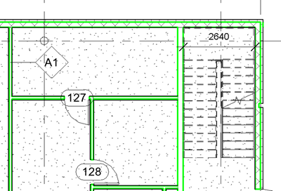
Just as roofs, floors, and ceilings can consist of multiple horizontal layers, walls can consist of more than one vertical layer or region. You can use various tools to modify the structure of vertically compound walls. You can add, delete, or modify individual layers and regions, or add sweeps and reveals to customize the wall type.
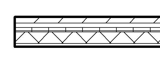
7-layer wall shown in plan view
Wall Layers
- Function - Defines how layers of compound element will join to adjacent compound elements. See About Applying a Function to a Layer of a Compound Structure.
- Material - Material assigned is used for graphics and analysis. See About Materials in Compound Geometry.
- Thickness - Defines how thick a layer is. Layers assigned a membrane function can have 0 thickness.
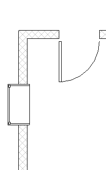
- Wraps - Controls if a layer will wrap on wall ends or at wall inserts (doors and windows). See About Layer Wrapping.
- Structural Material - One layer between the core boundaries of the wall can be set as the Structural Material. The physical asset of material assigned to this layer is used in the structural analytical model. Layers outside of the core boundaries of the wall cannot be assigned as a structural material.
- Variable - One layer of a compound wall can be set as variable. walls with only one layer can still be set as variable. When you do this, it enables the choice of Tapered, in addition to Vertical and Slanted, for the Cross section instance parameter of a wall. In the wall type properties, set the default angles (from vertical) desired for the interior face and exterior face of the tapered wall type. The angle will be applied to the variable layer of the wall. All layers except the variable layer will have constant thickness. See
Wall Type Properties.
If a variable thickness layer is set, you are not able to alter the vertical structure of the compound wall. Tools to Split, Merge, and Assign Layers will be disabled. See Modify Compound Walls.
Note: When using copy monitor workflows, the variable setting of a wall's layer will not be changed if the variable setting is changed in the linked file after the wall was copy monitored. In this case, the wall type must be changed manually or transfer project standards from the linked file.
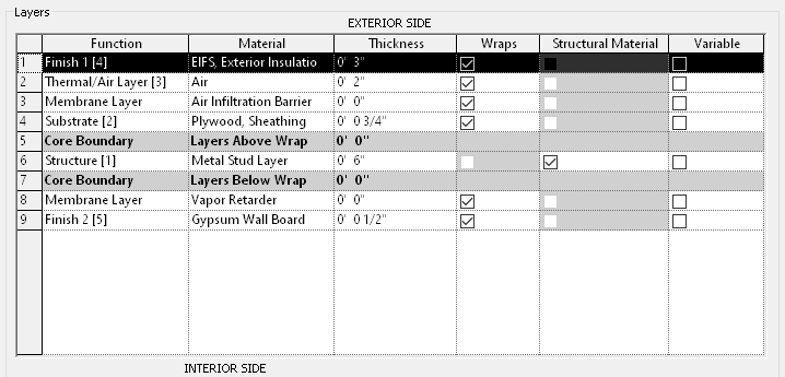
Layer rows: correspond to wall layers or regions

Wall layer: Constant thickness and extends the height of the wall.
Wall Regions

Regions: Finish layer of wall split into regions.
Wall Core
Wall layers positioned between the 'core boundary' rows in the Edit Assembly dialog define the wall 'Core'. The wall core definition is used when the core centerline or the core faces are used to establish the wall location line. See About the Wall Location Line.
Because core thickness can vary in vertically compound walls, the core centerline and core face location lines are determined by the core thickness at the bottom of the wall. For example, if the wall core is thicker at the top than at the bottom, and you specify the location line as Core Centerline, the centerline of the core is measured between the core boundaries at the bottom.
When dimensioning, the wall core center line and wall core faces are an optional setting for positioning the extension line.
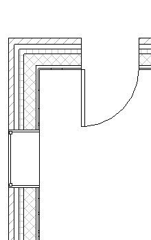 Non-core layers visible |
 Non-core layers overridden/hidden |
