Code Group Verification
Learn how to perform verification for groups of members in the service limit state.
Continue working in your project or open the project Frame_3D_Design.rtd.
Note: The Tutorial files are located in C:\ProgramData\Autodesk\Examples\TutorialsIn the Calculations dialog, select Code group verification option, and then type 1to4 in the same line.
In the Limit states group of options select SLS, in order to perform calculations for the service limit state, and then type the following loads:
Dead loads: 1,
Live loads: 4,
Total loads: 1to4.
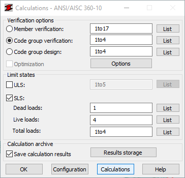
In the Calculations dialog, click Calculations.
The Code Group Verification dialog opens displaying the most significant information about the sections. The Messages tab (as shown below), contains important information for the next steps in the design process:
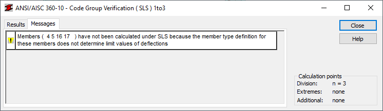 Note: The Member Type for Bracings does not determine limit values for deflections. The next step explains how to set these parameters in order to perform the verification as required.
Close the Code Group Verification dialog, and then in the Calculation Result Archiving dialog click Cancel.
calculation result can be saved in the calculation result archive. In this tutorial we will save the calculation result at the end of the verification process.
Click Design > Steel Members Design - Options >
 (Code parameters).
The Member Type dialog opens.
(Code parameters).
The Member Type dialog opens.Select Simple member, and then click
 (New steel member type definition).
The Member Definition Parameters dialog opens.Tip: Select the Member Type that is most similar to the new type that you want to create so that some of the basic properties are automatically applied.
(New steel member type definition).
The Member Definition Parameters dialog opens.Tip: Select the Member Type that is most similar to the new type that you want to create so that some of the basic properties are automatically applied.Type Simple member_1 in the Member type text box, and then click Service.
The Serviceability - Displacement limiting values dialog opens.
Select the following values:
- In the Deflection limits (local system) group of options, select the Absolute value for Dead, Live and Total Loads,
- In the Node displacement limits (global system) group of options, select the Relative value for Total Loads.
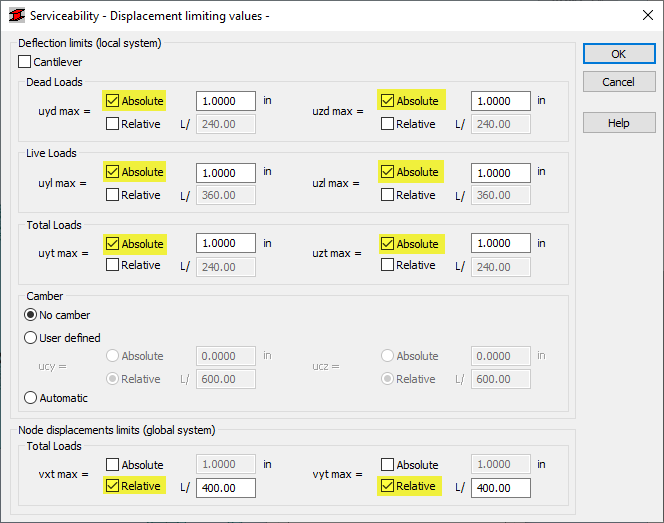
Click OK.
Click Save and close the Member Definition Parameters dialog.
The new member type is now listed in the Member Type dialog box.
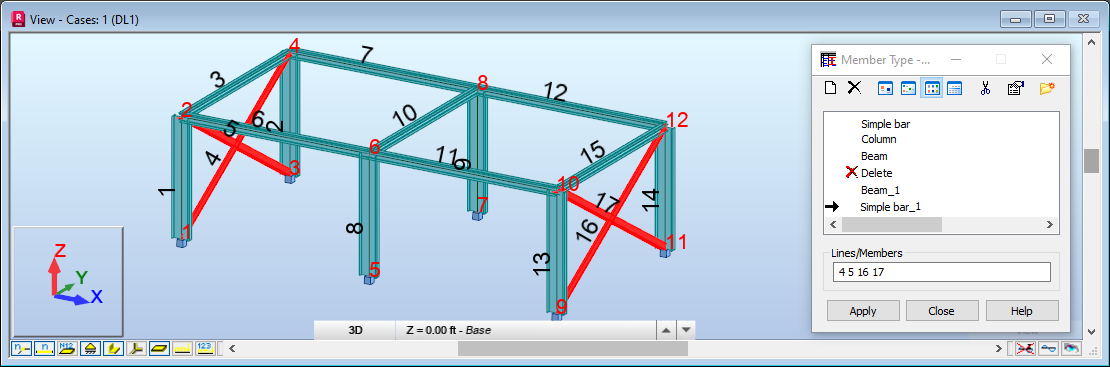
Ensure that Simple member_1 is selected, type 4 5 16 17 in the Lines/Members field as shown below.
Alternatively, place the cursor in the Lines/Members field, then go to the drawing area, and hold the Ctrl key to select bracings with numbers 4, 5, 16 and 17.
Click Apply, and then click Close.
In the Calculation dialog, click Calculations.
Results of the Code Group Verification are shown below.
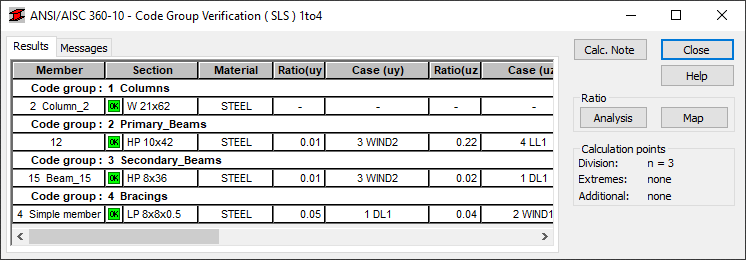 Note: All sections are now properly defined for all the groups of members.
To visualize the detailed results for a selected group, click 4 Simple member_1_4 in the Bracings group.
The row is highlighted in black and the Results dialog is displayed:
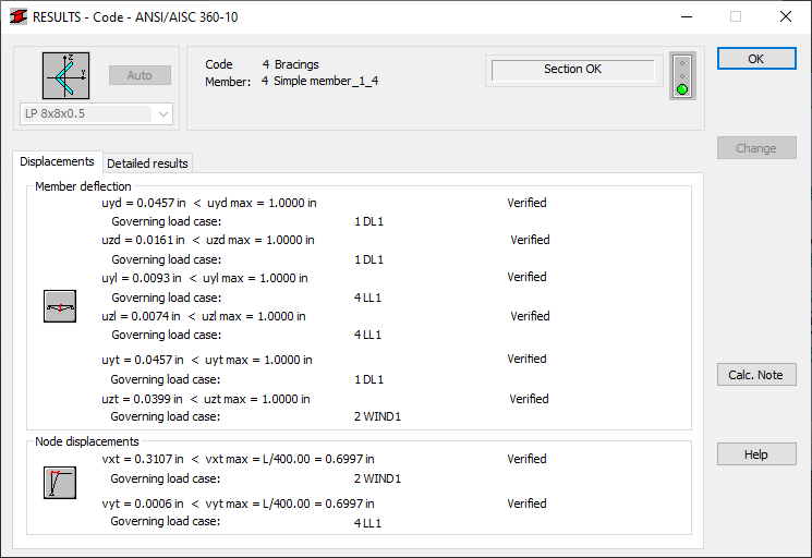
Review the results, and then click OK.
Close the dialog, and then click Save in the Calculation Result Archiving dialog.
A final calculation result is saved in the calculation result archive.
Save the project as Frame_3D_Verification.rtd.