Cavitation
The cavitation model that is used in Autodesk® CFD is described in Reference 3. To summarize, cavitation is represented by the presence of spherical vapor bubbles of a fixed radius. These bubbles are formed on the non-condensable gas particles present in the fluid. Hence, there are 3 components in a cavitating flow: non-condensable gas (denoted by the subscript "g"), liquid phase (denoted by the subscript "l") and a vapor phase (denoted by the subscript "v"). It is assumed that the mass fraction of the non-condensable gas is fixed and well mixed in the fluid. With this assumption, the liquid phase and the non-condensable gas can be combined into a single volume fraction  . This volume fraction is tracked using a scalar transport equation:
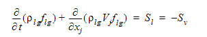
 where is the density of the combined non-condensable gas and liquid phase
 is the velocity vector
 is the source of liquid phase (this is the vapor region condensing)
 is the source of vapor phase (this is the liquid phase evaporating)
The liquid phase source term, is written as:

 is the density of the vapor phase
 is the average bubble radius
- p*v*** is the vapor pressure of the liquid
- p is the local pressure
 is the liquid density
 is the volume fraction of the non-condensable gas
 is the volume fraction of the vapor phase
Once the volume fraction is calculated, the density of the mixture can be calculated. This density is then used to solve the continuity, momentum and other scalar equations. Autodesk® CFD can be used to plot the volume fraction of the vapor phase, .
Contour plots of this volume fraction show areas where the cavitation bubbles are present. The value of this volume fraction represents the fraction of the local fluid volume that contains bubbles.