Inlet Flow Condition
In this step, we assign a velocity to the inlet surface.
Click Boundary Conditions from the Setup tab:

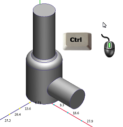
To resume the visibility of all parts, press Ctrl, and middle click anywhere off the model.
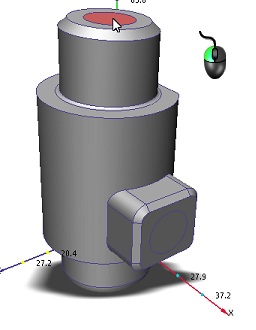
Select the inlet face by left clicking on it:
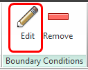
Click Edit from the Boundary Conditions context panel:
On the Velocity Magnitude line, enter 1000. Click Apply:
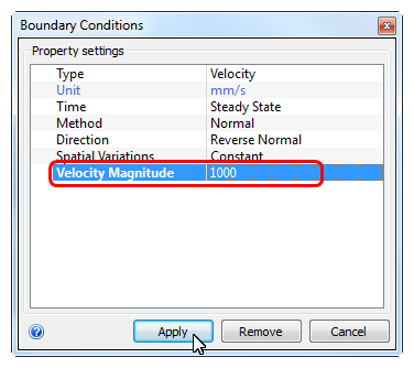
What it should look like...
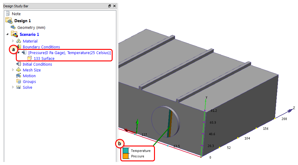
To verify that the boundary condition is properly assigned to the inlet, check the Design Study Bar and the colored stripe on the inlet surface:
On the Design Study bar, confirm the value for the condition on the inlet.
The stripe on the inlet face should correspond to the boundary conditions type in the legend.
For this exercise, we applied a constant velocity. In many valve simulations, either the flow rate or the pressure drop is known. Either condition can be used as necessary instead of a specified velocity. (Just don't apply more than one flow condition to the same inlet.)