Heat Sink Material - Micro Channel Example
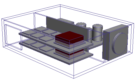
The following image shows the electronics assembly, from the Electronics tutorial, with some transparent walls.

There are two of the same Printed Circuit Boards (PCB) in the assembly. Each PCB has a chip cooled by an aluminum heat sink. The heat sink is attached to the chip using a solid aluminum spacer with the same footprint as the heat sink.

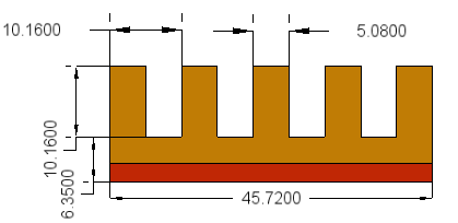
To apply a heat sink material, first replace the modeled heat sinks and spacers with simplified geometry in your CAD model. Since the modeled heat sinks have a thick base plate, a two-part block assembly is appropriate (see Heat Sinks for details on choosing single blocks or two-block assemblies). The top block represents the finned area while the bottom block represents the base plate and spacer. The two-part assembly has the same envelope dimensions as the combined heat sink and spacer.
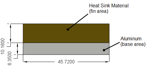
Once you have created or updated your CAD model in Autodesk® CFD, assign and create the heat sink material to each of the fin area blocks.
Click Materials from the Setup tab.
Select one of the fin area blocks and open the Materials dialog.
In the Materials dialog:
- Select Heat Sink for Type.
- Click Edit on the Material line.
In the Material Editor dialog, Material section:
- Enter micro channel sink for Name.
- Select My Materials, or another custom database, for Save to database.
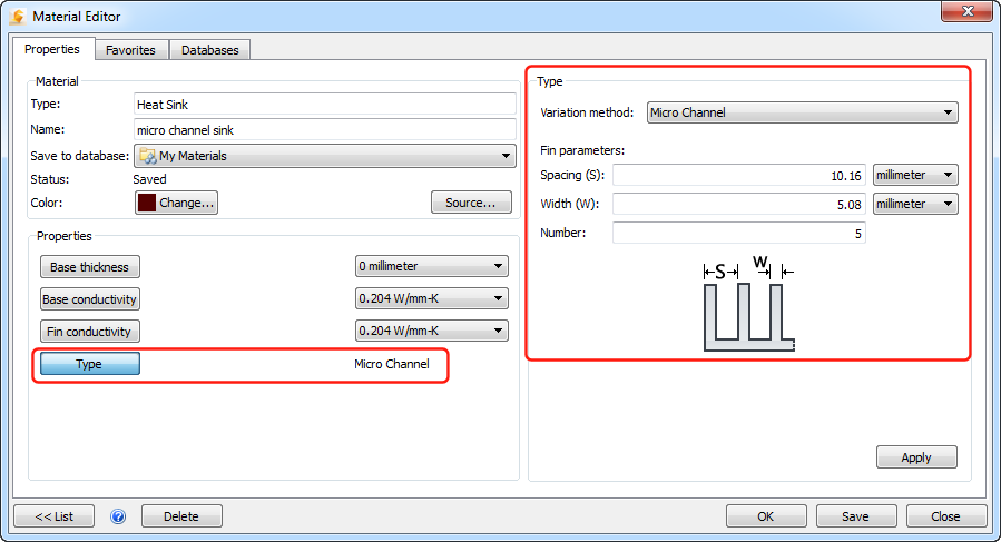
In the Material Editor dialog, Properties section:
Set Base thickness to 0 and click Apply. With a two-part assembly, the base area is explicitly modeled by the solid aluminum block. As a result, you do not want the heat sink material correlation to include base effects.
Set Base conductivity to 0.204 W/mm-K (value for aluminum) and click Apply.
Set Fin conductivity to 0.204 W/mm-K (value for aluminum) and click Apply.
Set Type to Micro Channel, enter the Fin parameters that correspond to the physical heat sink and click Apply:
Click OK.
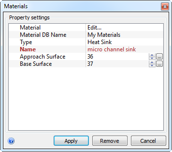
In the Materials dialog:
Verify that the Name is micro channel sink.
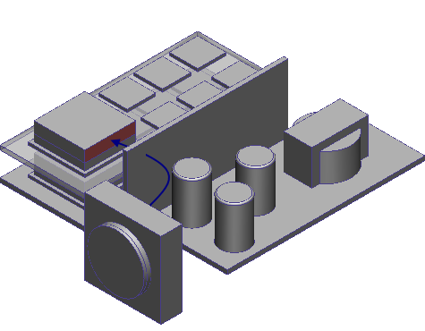
Click the number for the Approach Surface. The Approach Surface dialog opens.
Click Select Surface and choose the upstream or approach surface. For this example, air flow passes through the center baffle and approaches the surface as shown in the following figure.
Click the number for the Base Surface. The Base Surface dialog opens.
Click Select Surface and choose the surface that interfaces with the aluminum base area block.
Click Apply.
Note: You can only assign heat sink materials to blocks immersed in fluid. If an error dialog appears, when you click Apply, assign a fluid material to the volume surrounding the block. Repeat the process of assigning the heat sink material.
Select the other fin area block and assign the micro channel sink material to that block.
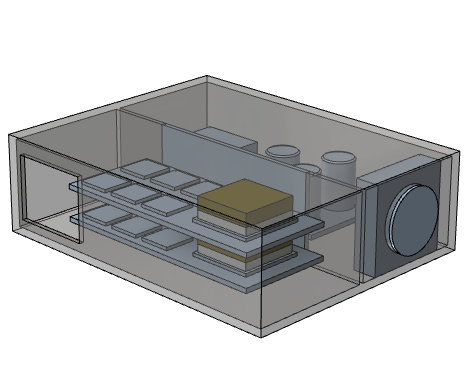
The following figure displays the electronics assembly with the micro channel sink material and aluminum assigned to the fin and base areas, respectively.
