Void Fill
The typical CAD model consists of the solid parts, but not fluid parts. The fluid region is usually contained within and around the solids, but in most cases is not explicitly constructed as part of the geometric model.
Geometry that consists only of solid parts will typically have openings where the working fluid (air, water, etc.) will enter and leave:
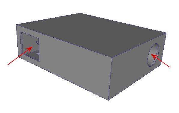
In this state, such a model is not suitable for a flow analysis (because of the lack of a flow part).
The Void Fill tool provides a facility to create capping surfaces that bound a water-tight internal void. The surfaces and volume that are created are actual geometry that can have boundary conditions, materials, etc., and are meshed as part of the simulation model.
To access Void Filling, click Setup > Setup Tasks > Geometry Tools, and click the Void Fill tab.
Alternatively, right click on the Geometry branch of the Design Study bar, and click Edit...
Void Fill is a two step process:
Step 1: Create the Capping Surfaces
Capping surfaces must be planar, and cannot overlap any other surfaces.
For each opening, select the edges that bound the opening. Only edges that contact the first selected edge of an opening and are co-planar with it can be selected.
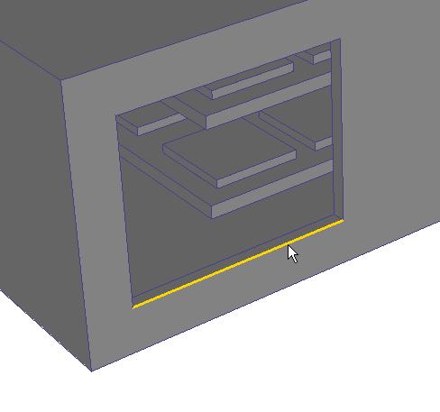
Auto-close attempts to automatically identify the remaining edges needed to close the surface loop.
In the image above, there are two possible paths that will create a planar surface. Because the loop is ambiguous, Auto-close cannot automatically close it...
After selecting the next edge, the entire loop is no longer ambiguous, and can be automatically completed:
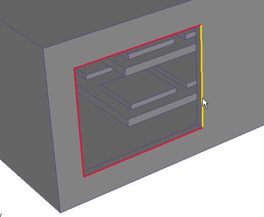
Build Surface becomes active when a loop is completely defined. Click it to build the surface.
Repeat the process for the remaining openings.
Step 2: Complete the Internal Volume
When all bounding surfaces are complete, click the Fill Void button.
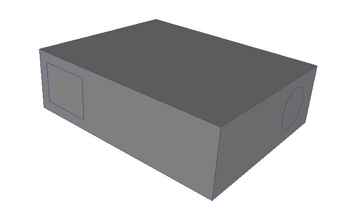
If the void fill region is constructed, the following message is written to the Output bar:
“Fill Void Successful; there were 1 part(s) created.” (The actual number of created parts will be written in the message.)
Regions created with the Void Fill tool are added to the Parts branch, and are named Volume. They are part of the simulation model, and can be meshed.
For an example using Void Filling...