Defining Flow-Driven Linear Motion
The motion of flow-driven objects is influenced by the flow as well as user specified driving and resistive forces. The origins of such forces do not have to be included in the analysis model--the forces act on the object in a user-prescribed manner to either push the object in its prevailing direction or to impede its progress.
In several places in this section, the Direction Vector of the object is referenced. This is the direction specified on the Motion task dialog. Because the true direction of flow-driven motion is not always known prior to the analysis, this direction is really the Reference Positive Direction. Directions of driving and resistance forces are then relative to this direction.
Flow-driven objects may start off moving at a known velocity, and either speed up or slow down based on their interaction with the surrounding fluid (and applied forces).
To open the Motion Editor:
- On the Motion quick edit dialog, set the Type to Linear, and check Flow-Driven.
- Click Edit... on the Edit Motion line.
To Define Flow-Driven Linear Motion:
- Three properties are available, but entries are not required for all: Initial Velocity, Driving Force, and Resistive Force.
- For each desired property, select the Variation Method, and enter the appropriate values. The Variation Methods are described below for each property.
- Click Apply.
- Click OK.
Variation Methods
Initial Velocity
If the object is in motion at the beginning of the calculation (and not starting from a dead-stop), the initial velocity should be specified. The object will travel at this velocity at the on-set of the calculation, and will react to the flow forces appropriately.
Driving Force
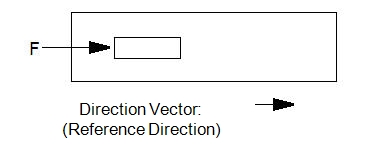
Driving forces are forces that are positive when acting in the direction of motion specified on the Motion task dialog. A negative driving force will act in the opposite direction.
Examples of driving forces include electromagnetic and other body forces as well as forces imposed by objects omitted from the analysis geometry. The force will act in the same direction as the direction of motion (as specified on the Motion task dialog):
A driving force can be used to represent the force of gravity on an object by specifying the weight of the object as the driving force, if gravity is acting in the direction of travel.
The variation methods for Driving Force are described:
Constant Variation Method:
Enter a constant force value to apply an unchanging force to the object throughout the entire analysis.
Table Variation Method:
If a driving force is to vary with time, enter the time history as a table of driving force and time. As with all table entries, the values can be retrieved from or saved to an Excel “.csv” file.
Resistive Force
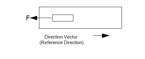
Applied resistive forces affect the motion of the object by acting against its specified direction of travel, impeding its progress. A positive value of a resistive force acts in the opposite direction of travel; a negative value acts in the direction of travel.
In addition to constant and tabular specification, resistive forces can be specified as a spring. This is a virtual spring, and does not exist in the geometry model.
A resistive force can be used to represent the force of gravity on an object by specifying the weight of the object as the resistive force, if gravity is acting opposite the direction of travel.
The variation methods for Resistive Force are described:
Constant:
Enter a constant force value to apply an unchanging resistive force to the object throughout the entire analysis.
Table:
If a resistive force is to vary with time, enter the time history as a table of resistive force and time. As with all table entries, the values can be retrieved from or saved to an Excel “.csv” file.
Spring:
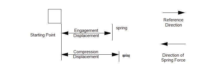
Four parameters are required to specify a spring:
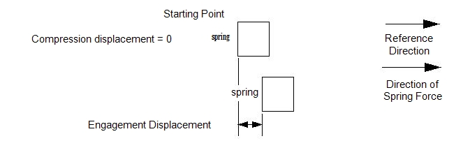
- Engagement Displacement: the distance traveled before touching the spring
- Compression Displacement: the distance traveled before fully compressing the spring (relative to the starting point). This is the limit of travel, and is considered a hard stop.
- Engagement Force: the amount of force the spring exerts at the engagement displacement. (This is the spring pre-load. If none exists, enter 0).
- Compression Force: the amount of force the spring exerts at the compression displacement.
Recall that the Direction Vector specified for flow-induced motion is the reference positive direction. Depending on the flow, the true direction of the object may change. However the Direction Vector specified on the Motion task dialog is really a Reference Direction for the signs of applied forces and displacements.
Because springs are typically a resistive force, a positive spring force will act in the direction opposite of travel of the object’s reference direction; a negative spring force acts in the reference direction.
Likewise, a positive displacement is in the reference direction; a negative displacement value is opposite to the reference direction.
Note that all spring displacements are relative to the initial position defined using the Initial Position slider on the Motion task dialog.
The following diagrams describe setting up several scenarios involving springs.
If the object is not touching the spring at time = 0, then the configuration may appear as:
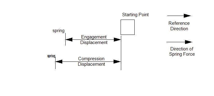
If the object is touching the spring at time=0, then the engagement displacement is 0:
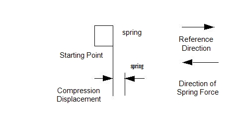
If at time = 0 the spring is fully compressed by the object, then the compression displacement is zero, and the engagement displacement is the distance to where the spring is no longer compressed:
If the object has to travel in a direction opposite of its Reference Direction to contact a spring, then the displacements should be applied as negative values:
Note that only one spring is allowed on a moving part. Because of this, a forward and backward spring cannot be applied to the same part.
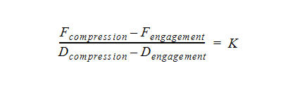
The relationship between the required parameters and the spring constant is given as:
Related Topic:
Example showing how to define a Motion with resistive spring