Free Surface
With the Free Surface modeling capability, you can dynamically simulate the interface between liquids and gases. This ability is essential for modeling flow phenomena such as waves, sloshing, and spilling. These are flows that occur in nature as well as in a wide range of engineering applications.
Examples of Free Surface Applications
You can use Free Surface to simulate many different applications. Here are several examples:
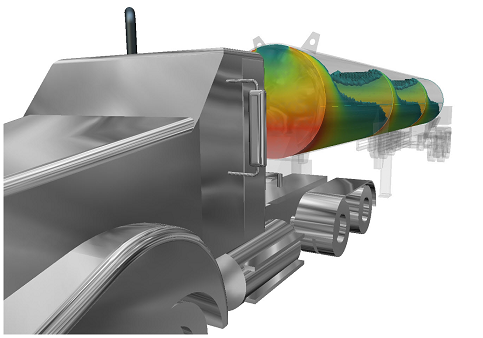
Liquid movement within tanks
- Sloshing: How a liquid moves in a partially filled container.
- Agitation: How a liquid behaves in a tank with submerged or partially submerged agitators, baffles, and/or multiple inlets and outlets, or by tank motion. (Examples of tank motion include seismic effects and mobile tanks in transit.)
- Mixing: Concentration of different liquid species.
Water Transport & Infrastructure
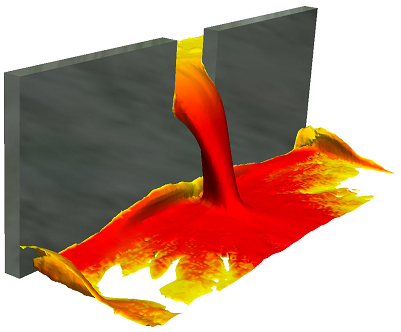
- Civil structures: Dams, culverts, spillways, and weirs.
- Valves: Open channel flow.
- Water Tanks: Fill/draw cycles or continuous inflow and outflow.
Setting up a Free Surface Simulation
When constructing and setting up the model, consider the model in terms of the liquid. Be sure to include the liquid regions in the CAD model. Assign materials and boundary conditions based only on the liquid. Consider regions occupied by gas (air) to be void of liquid.
- Assign a liquid material to the parts that contain or will contain fluid. Do not assign a gas material to a part if it currently contains or will contain liquid. CFD does not allow multiple materials to be assigned to the same part.
- To indicate where the liquid enters the domain, specify a flow boundary condition (velocity, volumetric flow rate).
- If the domain is full or partially full at time = 0, specify a Height of Fluid initial condition to indicate the initial location of the liquid. Create the geometry such that a distinct volume exists for the initial liquid level. Note that to access the Height of Fluid condition, change the selection mode to Volume.
- If the tank is empty at time = 0, assign the liquid material to the volume, but do not assign a Height of Fluid initial condition. The liquid enters the domain because of the specified flow boundary conditions.
- Mesh all fluid parts and parts that the liquid will occupy, even partially. The mesh requirement for free surface simulations is high. A fine mesh is required in regions where the liquid and air interact. Be sure to define a fine mesh distribution at the liquid-gas interface as well.
CFD runs free surface simulations as transient, and automatically computes the time step.
To enable Free Surface:
- Open the Solve dialog box (Setup (tab) > Simulation (panel) > Solve).
- Click Free surface on the Physics tab.
- On the Free Surface dialog, check Enable free surface.
- Specify the acceleration forces acting on the liquid by setting the Gravity vector. You can also specify more acceleration components with the Acceleration settings. These commands are useful for simulating body forces such as in a moving tank. Click here for more about the Free Surface dialog.
- The "ADV 1" advection scheme is enabled by default, but it is a good idea to verify that ADV 1 is enabled for your simulation. To do this, click the Control tab on the Solve dialog. Click Solution Control, and click Advection... on the Solution Controls dialog. Select ADV 1 if it isn't already selected.
Visualizing Free Surface Results
After the free surface simulation is complete, you can visualize the resultant liquid volume.
- To view the shape of the flow, right click off the model, and select Free Surface:
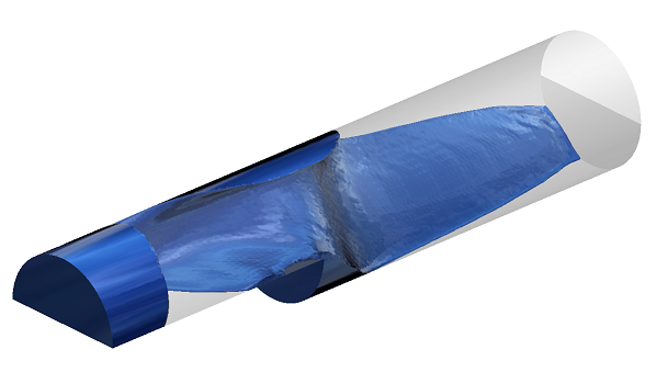
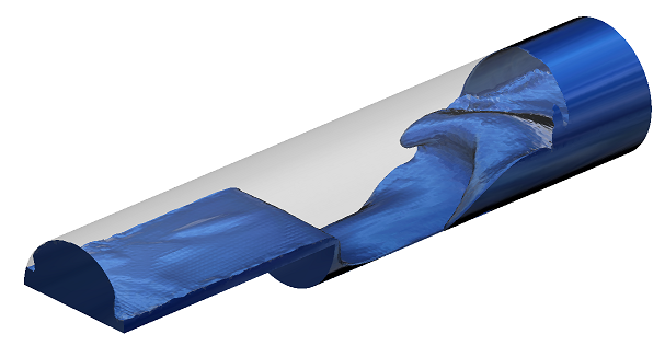
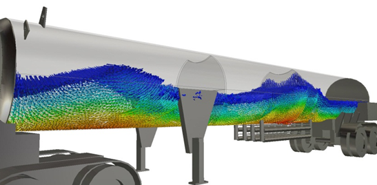
To display the VOF result quantity, right click, and select VOF from the Result menu. The liquid-gas boundary is represented by a VOF value of 0.5.
To see the liquid movement, display VOF as an iso surface, and enable vectors:
Limitations of the Free Surface Functionality
Physically, the free surface phenomena covers a wide range of physical applications. However, there are some limitations in the simulation model. The Free Surface model does not simulate the following applications:
- Sprayers and nozzles
- Air/Fuel mixing and atomization
- Droplet and rain transport due to wind
- Paint adherence to walls
- Surface tension
- Pin hole or thin slot venting for casting or filling simulations
Example of a Free Surface Simulation
At the start of this example, the reservoir on the left is full, and the one on the right is empty. The reservoirs are separated by a retaining wall with a gate cut-out to allow water to pass between the reservoirs.
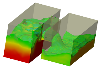
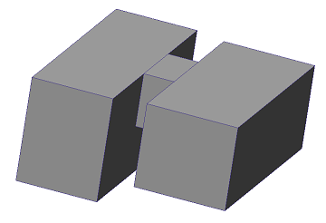
Geometry: The two reservoirs and the pass-through gate were created as separate parts in the CAD system.
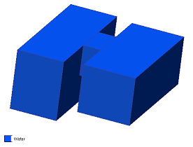
Materials: Water is assigned to all three parts.
Boundary Conditions: There are no inlets or outlets because the flow is contained within the domain. No boundary conditions are applied. Note that a pressure condition is automatically applied at the liquid-air interface, so it is not necessary to apply an additional pressure boundary condition in this model.
Initial Conditions: Because the reservoir on the left starts full of water, apply the HOF initial condition to it.
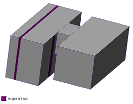
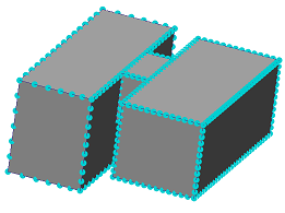
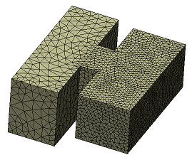
Mesh Sizing: Use Automatic Sizing, but refine the mesh where the air and water will interact. In this case, that is primarily in the gate and in the right-side reservoir.
Solve:
- On the Physics tab of the Solve dialog, click Free surface, and check Enable free surface.
- Specify a gravity vector. In this case, gravity acts in the -Z direction, so set the Earth gravity directional unit vector to 0,0,-1.
- On the Control tab, the Solution Mode is automatically set to Transient, and the Time Step Size is automatically set to 0.01.
- If you wish to animate the results, specify a value for Save Intervals > Results.
- Specify the number of time steps (1400 were used for this simulation), and click Solve.
Results:
- To view the shape of the flow, click Iso Volumes from the ribbon, and create an Iso Volume. Click Enable Visualization from the Free Surface context panel in the ribbon.
- To animate the filling process, right click off the model, and Animation. On the Animation dialog, click Animate, and the Play button. (If you do not specify a value for results Save Intervals, you will only be able to see the last time step in the simulation.
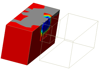
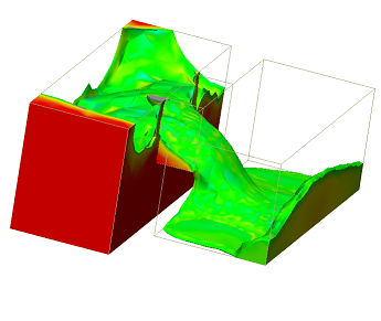
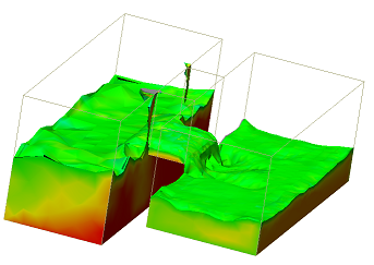
As you can see, the water flows from the left reservoir into the right reservoir until the water level in the two is the same.