Summary Images and the Design Review Center
In traditional CAE tools, comparing results from multiple analyses often involves manually setting up a view from every analysis in the exactly the same manner and then comparing them side-by-side. This can be a challenging process for large, complex simulations.
With Summary Images and the Design Review Center, you can review results from multiple scenarios much easier than the traditional approach. The Design Review Center is structured to allow simultaneous comparison of many Scenarios. This means that it is easy to compare results from dozens of Scenarios at a time. The basic process is summarized:
- Prepare for the review by creating relevant results views on one of the Scenarios in your Design Study.
- Compare your results for all scenarios in the entire Design Study. Summary Images ensure that each result image is shown consistently for every Scenario.
- Conclude the review by understanding how each Scenario performs, and by selecting the one that satisfies the design criteria.
Example
An example showing how the Design Review Center can help is a design study involving a pressure relief valve. Several designs are evaluated, each with a slight variation of the shape of the flow passage. The objective is to minimize pressure drop and flow swirl.
After running the Scenarios, a Summary Image with a results plane showing pressure and particle traces is created. The Summary Image is opened in the Design Review Center. The results were presented on every Scenario in the study, making it easy to select the design that produces the best results.
Using the Design Review Center
Create your results view using the tools in the Results Visualization task.
To save the view as a Summary image, click Results (tab) > Image (panel) > Summary Image. (Alternatively, right click off the model, and click Capture summary image.) This adds the image to the Summary Images branch of the Decision Center.
Click the Decision Center tab to view the Decision Center in the Design Study bar.
Note: By default, each Summary Image shows results from all scenarios. To select specific scenarios for a Summary Image, right click on its branch, and pick Select scenarios... Select only the scenarios you wish to compare from the list.To map the Summary Image across all scenarios, right click on the Summary Images branch, and click Update all images. If you have multiple Summary Images, and want to save time by not updating all of them, right click on a specific image branch, and click Update image.
A thumbnail image from each scenario appears in the Design Review Center. If a scenario has not been run or needs to be updated, a place-holder image appears instead.
The first image is shown in the Graphics window. To show the others, left click on each and drag into the graphics window.
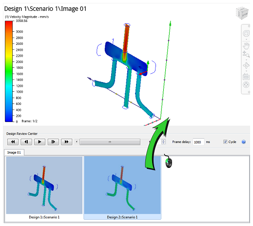
To compare the views, use the Design Review Center slider and animation controls.
To continue viewing results on a single scenario, click the Results tab.
Controlling Part Appearance
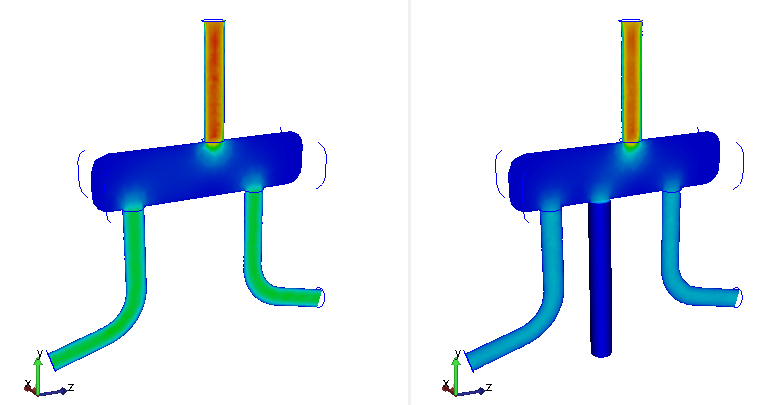
A Summary Image records the appearance of all parts currently contained in the active design. When a Summary Image is updated, the appearance of every part is applied to the other scenarios in the design study. However, if a scenario contains parts that are not in the captured scenario, those parts appear with a default appearance.
The viewport on the left contains the captured image; the viewport on the right contains a scenario with an additional part (displayed as shaded):
To change the appearance of a model or a specific part, use the standard appearance controls in the main menu or right click menu, respectively.
Notes
- Appearance changes are stored with the Summary Image. If resume standard interaction and then invoke the Design Review Center again, parts appear with the latest modifications. The same applies if Autodesk® CFD is exited and opened in a subsequent session.
- When a summary image is updated, all appearance modifications are removed, and the image is reset to its as-captured appearance. (The exception is for parts that do not exist in the originally captured image, as shown above.)
- To preserve appearance modifications when updating a summary image, right click on the thumbnail, and select Lock.
- To reset the summary image to its initial appearance, right click on the thumbnail, and select Reset.
- To reset the summary image to its appearance after the latest update, right click on the thumbnail, and select Reset.
- To adjust the legend settings, right click on the legend, and select Options...
Side-by-Side Viewing
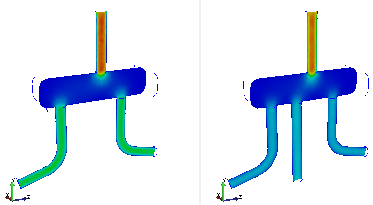
By default, a single view-port is active, and results are compared by flipping between views with the Design Review Center controls. This means that results from only one scenario are visible at a time. An alternative workflow is to compare results from different scenarios side-by-side. In many situations, this provides a more convenient way to compare results, especially when the differences are subtle.
To compare result sets side-by-side:
- Click View (tab) > Windows (panel) > Viewports. Select one of the Multi-View options from the menu (Vertical Split, Horizontal Split, etc.)
- Change the image in a view port by dragging an image from the Design Review Center tab into one of the view ports.
The viewport with the Autodesk® CFD icon in the lower right corner is the active view, and can be navigated. To activate a different viewport, simply click on it. To navigate multiple views together, click View (tab) > Windows (panel) > Link Views.