Extrusion
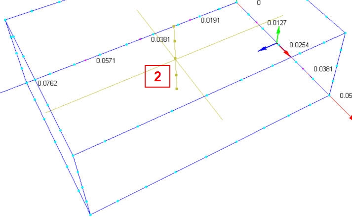
Extrusion meshing stretches triangular faces into multiple layers of wedge (prism) elements through the length of three dimensional parts with a uniform cross section. Extrusion meshing greatly reduces the element count in high aspect-ratio parts, and improves flow accuracy in models dominated by skin friction drag, such as pipe flow.
Extruded meshes are structured meshes, but can contact or even be immersed in regions meshed with unstructured tetrahedrals. This is called “non-conformal” meshing, and is a condition in which the nodes in the extruded section do not line up automatically with the surrounding mesh. Autodesk® CFD detects and deals with this situation automatically.
It is not possible to change the mesh in a model containing extruded regions and continue from a saved analysis. When the mesh is changed, it is necessary to start the analysis back at the beginning.
Assuming the geometric constraints are met, extrusion meshes can be used on moving objects and for solids in rotating regions (such as fan blades), but not the rotating region itself.
Assigning Extrusion:
In its most automatic form, the Extrusion capability computes both the end mesh distribution and layer growth based on the geometry. Manual controls are also provided that enable control of layer growth, end biasing, and the number of extrusion layers.
Available after Automatic Mesh Sizing has been invoked, select one or more volumes for extrusion, and click the Extrude mesh button on the Mesh Sizes quick edit dialog.
Automatic Enabled (checked)
The Automatic check box controls the operation of the dialog: when it is checked, the Automatic Sizing controls the number of layers and the end layer sizes. When unchecked, additional controls are available.
In Automatic mode, the Automatic Sizing feature matches the layer sizes originating at each end of the part with the length scales used in the surface mesh at each respective end.
- Modify the growth with the Growth slider if more or less layer stretching is desired. The default is 1.3.
- Select the Extrusion Direction, if applicable.
- While this dialog is open, the interactive Extrusion Preview line shows on the model.
- Click OK to close the dialog and assign extrusion to the selected part.
Automatic Disabled (unchecked)
When Automatic is disabled, more control is provided over the number and size of extrusion layers.
Modify the growth with the Growth slider if more or less layer stretching is desired. The default is 1.3.
Select the Extrusion Direction, if applicable.
Select the type of End Layering.
Select the number of Layers.
Note: The minimum range of the slider is 10. To specify fewer layers, enter the desired value directly in the adjacent text field.While this dialog is open, the interactive Extrusion Preview line shows on the model.
Click OK to close the dialog and assign extrusion to the selected part.
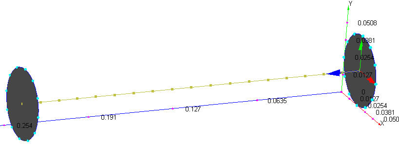
Extrusion Preview
A Preview Line is drawn through the part to indicate the layers. This is interactive, and updates as settings in the Extrusion dialog are adjusted. While this dialog is open, surfaces will blank on the active parts by right clicking on them to allow visibility of the preview. The Preview line below shows the extrusion for a Growth setting of 1:
Growth
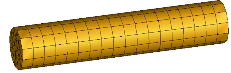
The Growth slider controls the degree of layer stretching through the part. When Automatic is enabled, the amount of acceptable growth also determines the number of layers. The growth value is a constraint which governs the maximum rate which the element layers can grow from one element to the next. The range of this slider is from 1.0 to 2, with a default of 1.3. At the minimum setting (1.0), the layers will be nearly the same size:
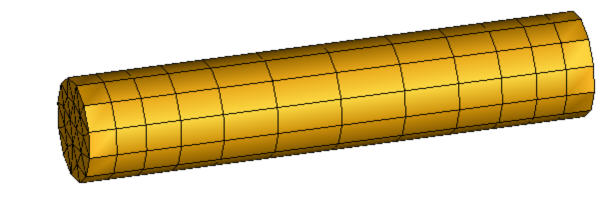
At the default growth (1.3), the layers will be approximately 30% larger in the part center:
The amount of growth from one layer to the next can be described with this equation:
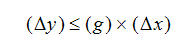
This means that the amount of growth of the next layer (y) is less than or equal to product of the growth parameter (g) and the amount of growth of the current layer (x).
At the maximum setting (2), the layers will be quite large relative to the ends:
When Automatic is unchecked, the number of layers is controlled with the Layers slider. The Growth parameter behaves differently than when Automatic is enabled, and does not represent a constraint. Growth values in the range of 20-50 are not considered extreme in many cases.
Extrusion Direction
The Extrusion Direction menu is available if:
- A single part is selected AND
- There are multiple possible extrusion directions, such as in a box.
If multiple parts with more than one potential extrusion direction are selected, Autodesk® CFD will automatically select the extrusion direction that is most closely aligned with the longest dimension of the part bounding box. If the variation in part bounding box dimensions is minimal, then the direction most closely aligned with the maximum dimension of the assembly bounding box is used.
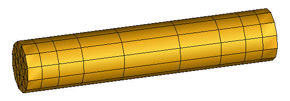
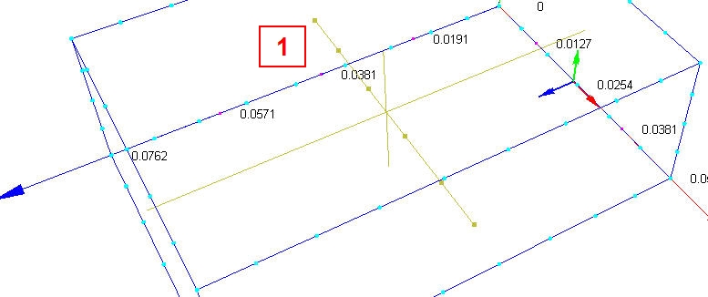
The Extrusion Direction menu lists each possible direction, and the preview line updates to correspond to the selected direction. Direction 1 is shown on the left, and Direction 2 is on the right:
End Layering
Available only when Automatic is unchecked, the End Layering menu controls the “biasing” of layers through the extrusion path. When a single part is selected, the options are:
- Uniform
- Small at End
- Small at Start
- Small at Both
- Small at Middle
The determination of the Start and the End of the part is based on the internal topological direction of the part, and is not user-controllable. The Preview line graphically indicates on which end the layers will be smaller.
When multiple parts are selected, only the Small at Both and Large at Both options are available.
Layers
Available only when Automatic is unchecked, the Layer slider controls the number of extrusion layers. The slider range is between 10 and 100. To specify a value outside of this range, simply type it in the field adjacent to the slider.