Refinement Regions
A basic guideline for a high-quality analysis model is that the mesh distribution must be sufficient to resolve the flow and temperature gradients efficiently. In regions where the flow moves in a single direction with little gradient, a coarser mesh is sufficient. In regions where the flow circulates or experiences large gradients (such as in wakes, vortices, and separation regions), a finer mesh is required.
Locally refining the mesh is not difficult if there are geometric features within the high-gradient flow. Simply refine the mesh on the volumes or surfaces. If there is no geometry in a particular region, create a mesh refinement region. These regions provide control of the mesh distribution, without the need to create additional geometry in the CAD model.
Mesh Refinement Regions are available as rectangular, cylindrical, and spherical volumes, and can only be used to make the local mesh finer.
It is important to note that Refinement Regions are not real geometry, and cannot hold any other settings (such as materials or boundary conditions).
Refinement Regions are available for models from all CAD types and launch methods.
The process for creating a mesh refinement region is divided into three steps:
Step 1: Add a Region
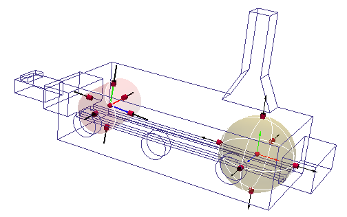
In this model, a wake downstream of the car requires a locally finer mesh. There is no geometry on which a finer distribution can be specified, so the resulting mesh is too coarse to accurately resolve the wake:
To create a Refinement Region in the anticipated wake area downstream of the car:
- Assign a mesh distribution to the model. (Click Autosize on the Automatic Sizing context panel.)
- Click Regions on the Automatic Sizing context panel.
- Click Add on the Mesh Refinement Regions dialog.
Step 2: Define a Region
Select the shape (box, cylinder or sphere) from the Region Type line.
There are two ways to define size, position, and orientation: graphically or by keying in values. A good technique is to use the graphical tools first and then "fine tune" by keying-in values.
Graphically
Use the Grab handles and a Coordinate Triad to positioning the region.
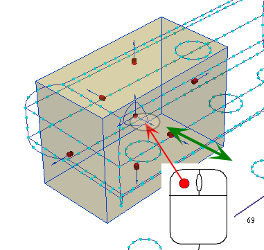
To resize a region:
- Click and hold the left mouse button on a grab handle.
- Drag with the mouse:

To move or rotate a region:
- Click and hold the axis or arc on the triad.
- Drag with the mouse:
Key-In
"Step 2" of the Mesh Refinement Regions dialog includes a table to define the shape, position, size, and orientation of the active region.
To define the shape
- Click in the right column of the Region Type row.
- Select the shape: Box, Cylindrical, or Spherical.
To define the position and size
- To define the position, specify the X Offset, Y Offset, and Z Offset.
- To define the size, specify the X Length, Y Length, and Z Length.
To define the orientation
You can use the angle commands to rotate the region:
- To rotate about the Z Axis, modify the +Z Angle.
- To rotate about the Y Axis, modify the +Y Angle.
- To rotate about the X Axis, modify the +X Angle.
Multiple rotations occur relative to the local axes of the region, not the global coordinate axes.
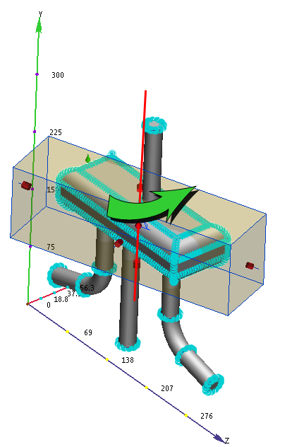
Example of multiple rotations:
Step 1: +Y Angle = 20 degrees
Starting from the default position, the region rotates 20 degrees about the global Y-axis.
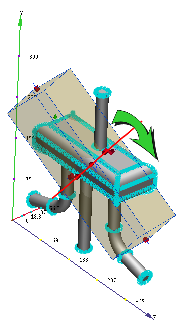
Step 2: +X Angle = 45 degrees
When we change the +X Angle to 45 degrees, the region rotates 45 degrees about its local X axis, and not the global X axis.
Step 3: Assign the Mesh Distribution
The mesh in a refinement region is based on the geometry enclosed within the region. To create a mesh with a single element size, click Uniform. Note that if the geometry has small features, and the region is large, the overall mesh count can be quite high.
To allow the mesh size to vary to produce a more efficient mesh, disable Uniform.
To define a varying mesh:
- Uncheck Uniform.
- Click Get local mesh size.
The resultant mesh grows from the smallest to the largest sizes within the region.
To define a uniform mesh:
- Check Uniform.
- Click Get local mesh size.
The resultant mesh uses the smallest size in the region.
To finish the mesh definition:
- Adjust the mesh density with the slider.
- Click Spread changes to propagate the effect of the mesh on the region.
If a Refinement Region is moved or resized after sizes are assigned, the sizes will be removed, and the distributions will no longer appear on the region. This is to ensure that the relative sizes (between the region and the surroundings) are always consistent with each other.
To modify an existing mesh refinement region
- Right click on the entry in the Design Study bar (under Model mesh settings), and select Edit.
- After modifying the region, rebuild the mesh definition.
Example
In this external aerodynamics simulation, a refinement region is created downstream of the car. The purpose is to better represent the flow in the highly turbulent wake region.
The mesh produced by the refinement region:
In the results, the separation downstream of the car is well defined. This concentration of mesh also helps to improve the accuracy of the drag on the car.
Related Links
Example using Mesh Refinement Regions