Tabs
Use the tabs to the right to for specific grouped options for materials, lights, etc.

General (tab)
Provides the location where hotkeys for variant sets can be defined.
- Hotkey - Where hotkeys for switching between variant sets can be defined. The first box is for a modifier key, such as Alt or Ctrl, while the second is for selecting an alphanumeric character for the shortcut. The second field is required to assign the hotkey (for example, a letter or sign).
- Comment - Adds a custom comment to each variant set.
- Screenshot (Go button) - Creates a quick rendering of the Render Window, using the currently selected variant set and render settings. VRED asks for a location and format to save the image, which is an 800x600 bitmap image, by default.
- Show in VR Menu and Streaming App UI - When enabled, variants and viewpoints are listed in the VR Menu and Streaming App UI. Disable this option hides them in the UI and make it easier for users to switch between relevant variants and viewpoints.
- Synchronize during Collaboration - Automatically synchronizes objects during a collaboration session. For an example of how to use this, see Synchronization during a collaboration session.
Geometry (tab)
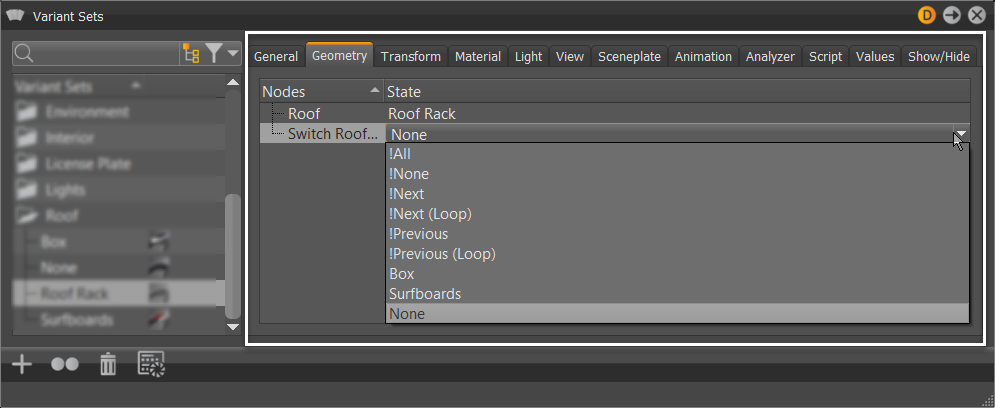
Creates or modifies the geometry variants. To create a geometry variant, drag a geometry node or group node to the right section in the Geometry tab.
Transform (tab)
Creates or modifies the transform variants. To add a transform variant to the variant set, drag a node with transform variants to the right section in the Transform tab. You can also drag a variant from the Transform dialog or from the Variants dialog to that section.
Material (tab)
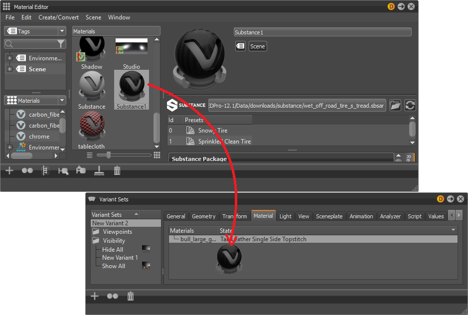
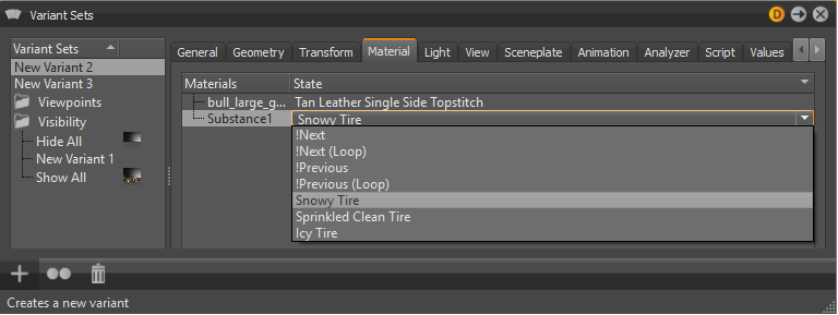
Creates or modifies the material variants. The supported types of materials variants are switch, Substance, and X-Rite materials. To create a material variant, drag a material node, such as a Substance, from the Material Editor to the right section in the Material tab.


Light (tab)
Creates or modifies the light variants. To create a light variant set, drag a light variant to the right section in the Light tab. Instructions for creating a light variant can be found in the Variant section.
View (tab)
Creates or modifies the Viewport variants. Viewport variants can be set within the View tab. Drag a previously created view into the Camera Editor to the right side of the View tab. Instructions for creating a Viewport can be found in the Camera Editor section.
Sceneplate (tab)
Creates or modifies the sceneplate (frontplates and backplates) variants. To create a new sceneplate variant set, a sceneplate can be dragged from the Sceneplate Editor to the right side of the Sceneplate tab. If this variant set is selected, the sceneplate will be set to active. If another variant set is activated, the new sceneplate will be set to active. It is possible to add multiple sceneplates to one variant set. It is also possible to add one sceneplate to multiple variant sets.
Animation (tab)
Creates or modifies the animation variants. To create an animation variant set, drag an animation from the Clip Maker (Clips icon) to the right side of the Animation tab.
Analyzer (tab)
Lets you enable, disable, or modify clipping planes within a variant set.
Clipping Plane - Contains the following options:
Enable / Disable Clipping - Enables or disables the clipping plane.
Only Clipping Values - Enables you to adopt value changes, but not its state (enabled/disabled).
Get Current Position - Adopts the position and orientation of the clipping plane selected within the Clipping module on feature execution.
Clipping Plane Position - Provides the coordinate position of the clipping plane.
Clipping Plane Normal - Affects the orientation of the clipping plane, in radians, about the X, Y, and Z axis.
Invert Direction - Toggles which side of the clipping plane is cut.
Hide scene - Hides the whole scene. Shows only the contours of the clipped objects on the clipping plane.
Show Clipping Plane - Toggles the visibility of the clipping plane.
Show Grid - Toggles the visibility of the clipping plane’s grid.
Show Contour - Toggles the outline of the objects cut by the clipping plane.
Script (tab)
For advanced users, each variant set can contain a Python script, executed automatically, each time the variant set is activated, whether through the Variant Set module, a hotkey, or another script.
Values (tab)
Add generic key/value pairs to any variant set, if the exported XML data should be processed personally (see Import and Export). The list of keys is on the left and values belonging to those keys are on the right. The currently selected key can be changed. Use the context menu to create or delete keys. VRED does not process this data in any way; it is only available in the exported Variants XML data.
Show/Hide (tab)
Shows or hides a list of Scenegraph nodes, based on whether Show Geometry or Hide Geometry was selected in the Variant Set context menu. This is especially useful for making screenshots of isolated parts of the model that belong to a specific variant set. Nodes can simply be added by dragging them from the Scenegraph into the list. They can be removed by using the context menu in the nodes list. Primarily, the Show/Hide tab is used in the Dissection Mode.