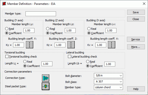
Use this dialog to define member type parameters for the American steel code EIA (Design of Steel Transmission Towers). There are two ways to access this dialog:
- Click the New member type option in the Member Type dialog
- Click the Parameters button in the Definitions dialog dialog.

The Member type field displays the name of the selected member type (enter any member type name).
The Buckling with respect to X, Y or Vaxis fields provide the length of the member for the required plane. The V axis constitutes the axis of the smallest inertia. Buckling with respect to this axis is important if axes are parallel to angle legs (e.g. angles of the CAE or L families). There are two ways to define the length:
- After the Real option is selected, the introduced value is interpreted directly as the length in question
- After the Coefficient option is selected, the introduced value is interpreted as the coefficient by which the real member length should be multiplied to obtain the length in question. For instance, introducing the value 0.25 means that the length in question equals ¼ of the real length.
Use the Coefficient option to define several members at a time, whose real length values differ, while their supports are distributed in the same manner. If the set parameters are to be saved as a category, it is necessary to select this option of length definition. Introducing the value 1.0 guarantees that each member defined by means of the category as Ly will assume its real length.
The Buckling length coefficient field defines the buckling length coefficients of a member in both directions (Ky and Kz). The real member length (i.e. the sum of component member lengths) is introduced automatically in the relevant fields.
Buckling length coefficient depends on the end-support condition of the bar nodes in the buckling plane. Buckling length is defined in the Buckling Type Diagrams dialog, and is opened by clicking the icon representing the selected buckling model type. Typical schemes of member support are included, and when one is selected, the coefficient value will be accepted or calculated automatically.
Buckling is always considered in calculations if a compression force appears in the member, even if it is negligible in comparison to the other internal forces. Separate analysis to determine if buckling effects should be disregarded, is not performed. To eliminate buckling effects from the calculations, the last icon must be clicked. If selected, buckling is disregarded in the calculation process.
Options used during member torsional and lateral buckling verification are selected in the Torsional Buckling and Lateral Buckling fields: parameters length Lr and length Lb respectively. Torsional and lateral buckling calculations are performed if the following options are selected: Torsional buckling check and Lateral buckling check.
The following connection parameters are available in the lower part of the dialog:
- Connection Type (clicking the icon results in opening the dialog in which a connection type can be selected)
- Steel Packet Type (clicking the icon results in opening the dialog in which a steel packet type can be selected)
- Bolt diameter
- Bolt class
- Member type (column leg, beam, truss element, redundant members).
Once the More button is clicked, an additional dialog is displayed, in which you can define code-determined member type parameters such as Anet/Agross ratio and Cm coefficient.
Once the Service button is clicked, an additional dialog is displayed, in which the member type parameters are defined (limit displacements, initial deflections).
Clicking the Save button results in adding a bar type - with defined name and parameters - to the list of predefined steel bar types.