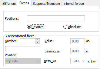
Click the Forces tab in the Detailed analysis (steel member design) dialog to display the following dialog:

Use this tab to verify that the concentrated forces are recognized correctly.
By default, automatic mode (the Loads/Automatic option) is active. Calculations include load cases defined by the user. All external and internal forces are read for the current load case(s) and only the forces are recognized during calculations.
Enter manual mode to introduce a new load case.
In automatic mode, you cannot change the position of load application along an element, or modify its value. Therefore, the Positions and Value fields are inactive. You can only change the information concerning the bearing width (Bearing ss field) and the position with respect to beam height (Position field).
The default coordinates indicate the location of forces and are defined in relative units. Multiple forces may have the same coordinate within one load case.
To define other load cases for calculations, click theListbutton. Once the new load cases have been selected, the set of forces are updated according to the defined selection.
Calculations will only cover forces that result in web or flange compression.
All forces are set to the top position (Forces/Positiontab) by default.
If a concentrated force is not transmitted locally (at a point) to the beam, but it is applied over a certain length, the length is defined in theForces / Bearing ss field.
You can also define the buckling length coefficient for the analyzed web (see: Concentrated forces / Beta_w). The coefficient will be used to carry out the analysis of the ribbed web under the concentrated force in question (Verification / Web stability for compression). It is possible to select the most common buckling length coefficients from the list or to define a new value for the coefficient.