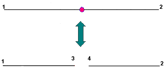
Hinge characteristics are defined independently for each degree of freedom. Defining a hinge for a selected direction divides an element into 2 elements and introduces double nodes to a structure model (see the image below).

After defining a hinge, there are additional, independent degrees of freedom, that is, displacements / rotations in nodes 3 and 4. For directions on which non-linear constraints have been defined, the relationship between the forces and a mutual displacement requires using the DSC (Discontinuity) element, that is a 2-node element where nodal forces are generated according to the formula:
Where:
![]() is a vector of force-displacement functions assigned to individual degrees of freedom.
is a vector of force-displacement functions assigned to individual degrees of freedom.
The element stiffness matrix is as follows:

Where:
- k = [ki]; i=1,Ndl is a vector of the stiffness assigned to individual degrees of freedom.
- T is a matrix of local-to-global-base transformations inherited from a bar element, and diag(k) is a diagonal matrix generated from the k vector.
This method of creating hinge characteristics applies to all degrees of freedom. a diagram can be composed of linear segments. It does not need to be continuous (in other words, changes of function values at a point are allowed).