This option defines linear releases in plate-shell structures. The released degree of freedom option for planar finite elements defines pinned connections between panels of plates and shells. Open the Linear Releases dialog using either method:
- Click Geometry > Additional Attributes > Linear Releases.
- Click
 .
.

Linear releases can be defined on:
- Contour lines
- Edges of objects (generated by extruding or revolving options)
- Cut edges generated from combining objects
Releases can be defined on elements of panels or selected walls of objects that have been generated during edit operations.
Releases between planar finite elements use additional finite elements of a new DSC (discontinuity) type. These are linear 2- or 3-node elements that implement discontinuity with specified rigidity to a mesh of planar finite elements. Elements of this type define unilateral releases or releases with specified elasticity.
If linear releases between panels have been defined in a structure, the results in the table of results for finite elements (belonging to the panels on which a release is defined) are displayed for calculation points. The calculation points are the nodes generated using the DSC algorithm, which is the basis for calculating structures with linear releases.
To display the numbers of the calculation points, select the Numbers of calculation points in the Display dialog (the option View > Display) on the Nodes tab.
In the Robot, it is recommended to use 3- and 4-node planar elements. When 6- and 8-node planar elements are used for mesh generation, the linear release option might not work correctly.
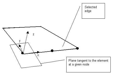
A release direction is defined in the local coordinate system specified by a highlighted edge line and a plane of selected panel finite elements.
You define the local directions for a release by selecting the edges. See the following image.

Where:
x - Direction tangential to an edge
y - Direction normal with respect to an edge in a tangential plane
z - Direction normal with respect to an element
Plate - Uz, Hx
Shell - Ux, Uy, Uz, Hx
For the remaining structure types (bar structures) this option is not available.
See also: Instabilities that may occur during calculation of a structure including linear releases
The top of the Linear Releases dialog has the following:
 - Defines a new linear release type.
  - Deletes a linear release type from the active list.
  ,
,  ,
,  , and
, and  - Displays the list of active linear releases as: large icons, small icons, a short list, or a long list.
  - Deletes from the active list all linear release types that are not in the structure.
  - Opens the Label Manager dialog.
You can define linear release 2 ways:
- Highlight an edge on which a release has been defined (using Assign mode: Manual)
A field for defining the edge lines on which a release is defined is in the dialog. Another field has a list of panels or walls of objects adjacent to the highlighted edge. To define a linerar release:
- Select a linear release type.
- Enter or highlight an edge line. If Name (number) of the edge field is active, the cursor changes its shape and the option of edge tracking is on.
- When an edge is selected, panels that adjoin the selected edge are entered in the List ofadjoining panels field. Panels in which a linear release is to be defined should be selected (using the appropriate options). Also, adjoining panels can be selected graphically
- Click Apply.
- Select the edge on which a linear release has been defined (using Assign mode: According to selection)
A field field containing a list of selected edges is located in the dialog. To define a linear release:
- Select an edge.
- Click Apply.
The linear release is assigned to all selected edges. Using this option, you can delete linear releases on many edges easily.
To delete a linear release from the structure:
- Click
 on the active linear release list,
 - Select an object in the structure you want to delete the linear release from
You cannot modify this type of linear release; it is assigned the same way as the release is to a structure element.
After the new linear release is added, its symbol displays.
See also: