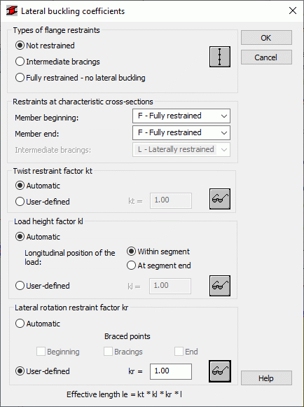
This option allows you to define distances between member cross-sections protected against torsion, that is the lateral buckling length for beams. To access the option, click either Upper flange or Lower flange in the Lateral buckling parameters field in the Member Definition - Parameters dialog.

You can define the following parameters in this dialog:
- Types of flange restraints field
- Not restrained - after selecting this option, a member is not restrained along the length against lateral buckling; a full theoretical length is used in calculations
- Intermediate bracings - after selecting this option, you can define positions of intermediate bracings; click this icon to open the Intermediate bracings dialog
- Fully restrained - no lateral buckling - after selecting this option, all options in this dialog are not accessible
- Restraints at characteristic cross-sections field
The selection lists (for the member beginning and end, and for intermediate bracings) in this field allow you to define a restraint type at these characteristic points; Based on selected values, Robot determines values of the kr, kl and kt coefficients following the recommendations in the tables 5.6.3.(1), 5.6.3.(2) and 5.6.3.(3) of the code
- Twist restraint factor kt field
During calculations, Robot automatically calculates a kt factor value based on the defined types of restraints at member ends and information about the section; You can also define this factor manually after selecting the User-definedoption; select the icon next to this option to open a window with the table 5.6.3.(1) of the code
- Load height factor kl field
During calculations, Robot automatically calculates a kl factor value based on the defined types of restraints at member ends, information about the load height (at the shear center or on the upper flange) and the position of a longitudinal load; You can also define this factor manually after selecting theUser-defined option; select the icon next to this option to open a window with the table 5.6.3.(2) of the code
- Lateral rotation restraint factor kr
During calculations, Robot automatically calculates a kr factor value based on the defined types of restraints at member ends and information about the points where the cross-section is restrained against lateral torsion; You can also define this factor manually after selecting the User-definedoption; select the icon next to this option to open a window with the table 5.6.3.(3) of the code