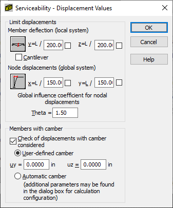
Click Service in the Member Definition - Parameters dialog to define additional code parameters determining displacement values (limit displacements) for timber members.

You can define the following limit displacements:
- member deflection in the directions:
- Y - use this field to define limit deflection of a bar in the direction of axis Y, depending on the length of the bar, e.g. L/200
- Z - use this field to define limit deflection of a bar in the direction of axis Z, depending on the length of the bar, e.g. L/200
- node displacements in the directions:
- X - use this field to define limit displacement of a bar node in the direction of axis X, depending on the length of the bar, e.g. L/200
- Y - Use this field to define limit displacement of a bar node in the direction of axis Y, depending on the length of the bar, e.g. L/200.
While determining member limit deflections, a member can be defined as a cantilever.
In certain structures it is necessary to increase displacements of structure nodes. The global coefficient Theta has been introduced due to this. Theta causes an increase in all displacements (the default value of the coefficient equals 1.5).
Note: The coefficient value is always θ ≥ 1.
Each node displacement can be calculated as:
In the lower part of the dialog, you can define parameters of members with camber:
- select Control of displacements with camber considered to take camber into account during member verification/design.
- to determine camber, do one of the following.
- provide the camber value in the User-defined camber field
- assume the calculated camber value on the basis of constant loads (Automatic camber).