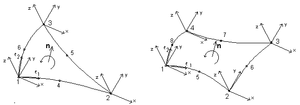
Every node has its own local system; therefore, the local coordinate system for an entire finite element is not required. It is important to know the orientation of the normal vector to the finite element surface. Preferably, normal vectors for all finite elements should have the same orientation. Otherwise, the load definition for an element (such as the pressure perpendicular to the surface of the shell) may be incorrect.
The orientation of a normal vector (perpendicular to the surface of a shell element) is determined according to the right-hand rule (in the direction first-to-last node of the element). Local coordinate systems and the orientation of the normal vector in respect to the surface of the element are shown in the following figure, presenting 6-node and 8-node finite elements.

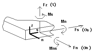
For planar finite elements, forces and stresses in an element are obtained. They are determined on the basis of location in respect to the local normal vector and to the tangential to the cross-section. The following sign conventions are adopted:
- n - The vector that is normal to the surface of the element cross-section
- s - The vector that is tangential to the surface of the element cross-section
- z - The normal, external to the element surface.
These vectors form a right-hand-rule Cartesian coordinate system. Positive orientation of forces, moments and stresses in a given cross-section are defined according to the orientation of the n / s / z vectors. This is schematically presented in the following figure. Forces, moments and stresses shown in the figure have positive signs.

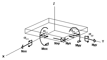
Results obtained for planar FEs are presented in local coordinate systems that may be defined and changed by the user in any moment of results presentation. For instance, positive orientation of forces and the corresponding stresses in a node are presented for the X axis as the reference direction.

See also: