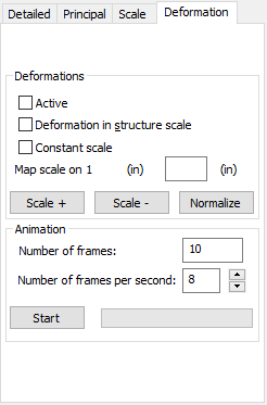
Select the Deformation tab in the Maps on Solids dialog to adjust map deformations.

You can use the following options.
- Active. Click to present deformation of the currently designed structure.
- Constant scale. Click to select the same scale for all presented diagrams. This is convenient when comparing the results obtained for a selected sectional force for different load cases. This is connected with the option Map scale on 1 cm (in). Determine the number of centimeters (inches) to which one centimeter in a drawing corresponds.
- Deformation in structure scale. Real values of structure deformation will refer to structure dimensions. This is connected with the Scale factor option. Specify a factor by which values of structure deformation will be multiplied.
- Scale +. Click to decrease the number of units per 1 cm of a diagram of the selected quantity
- Scale -. Click to increase the number of units per 1 cm of a diagram of the selected quantity
- Normalize. - Click to present maps of the selected quantities in such a way that the scale will be adjusted to the maximum and the minimum value of the selected quantity.
- Animation of structure deformation diagrams may also be presented on screen.
- Define the number of frames.
- Define the frame rate.
- Click Start.
When the animation is presented, transport controls are available to step through the animation. The animation of structure deformations can be saved in an *.avi format file. It is also possible to import and play an *.avi format file containing a previously-created structure deformation.
The difference between Map scale on 1 and Deformation in structure scale can be seen while zooming in and out of a structure. In Map scale on 1, the size of deformation remains unchanged. However, for the Deformation in structure scale, a deformation becomes adjusted to dimensions of a structure on the screen.