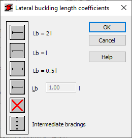
Use this option to define the appropriate section distances of a member reinforced against lateral buckling, that is lateral buckling length. Access this option by clicking one of the following keys: Upper Flange or Lower Flange found in the Lateral Buckling Parameters field of the Member Definition - Parameters dialog. The following dialog displays:

The dialog contains typical member support conditions based on the buckling length coefficients chosen. Due to the possibility of affixing the upper or lower flange separately and the occurrence of compressive stresses in either flange under various load cases, two lateral buckling lengths are available. The proper lengths are controlled by the coefficient by which the base length of the member should be multiplied to obtain the lateral buckling length. The length Iz is taken as the base length. You can either enter the coefficient value directly or it is chosen automatically by clicking the icon of the typical support conditions case.
To properly calculate the lateral buckling coefficient, it is necessary to define the lateral buckling length. Define the buckling length coefficient by clicking the icon and edit field provided.
Click  , to include in the calculations the bars with internal bracing (lateral stiffening of the analyzed bars, limiting the lateral buckling length). You can define the parameters for lateral stiffening, by double-clicking the icon and entering the information in the Internal bracings dialog.