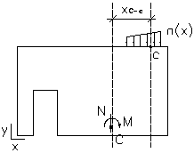
The module for RC wall design allows defining the following types of loads applied to the wall:
- Uniform loads are applied along the horizontal line on an arbitrary level of a wall.
- Planar loads are collected from the floor supported on the wall, transformed to uniform loads applied on any level of the wall.
- Reduced loads are applied in the plane of the wall base in the form of reduced sectional forces acting at the center of gravity of the bottom section of the wall.
- Uniform loads
Uniform loads and planar loads transformed to that form are distributed depending on a distance from the level where they are applied. It is assumed that in the case of an arbitrary shape of a load, its distribution along the wall height results in a uniformly distributed load.
The following drawing presents a pattern of distribution of gravitational loads along the wall height.

The angle q depends on whether a wall is reinforced. It is expressed by a value of the trigonometric function:
- tgθ = 1/3 for unreinforced walls
- tgθ = 2/3 for reinforced walls.
- Distribution of loads from lintels of openings
If there are openings in the wall, it is assumed that loads from the opening lintel are carried by the zones adjacent to the opening edges. Distribution of loads depends on load position with respect to vertical edges of the opening. The width of distribution of a load from the lintel (width of zones at the opening) is assumed as equal to the smaller of the two values: half the opening width and double thickness of a wall.
Such an approach allows taking account of stress concentrations. For example, as in zones adjacent to windows or between windows.
The RC wall module allows definition of loads that repeat on successive (higher than the considered wall) stories of a structure. For example, if loads from the floor supported on the wall are the same on all above stories, you can enter a number of identical stories above the considered one in the Number of stories above field in the dialog box for load definition.
In this case of the series load, it is assumed that distribution of loads transferred from higher stories onto the designed wall is uniform along the span length.
The method of calculation of stresses from uniform loads is illustrated by the formulas below:
γ(x) = p(x) / a(x),
where:
γ(x) - stress value at the x point
p(x) - value of a distributed load (of an arbitrary shape)
a(x) - wall thickness.
- Reduced loads
Reduced loads are loads transferred onto the whole structure adopting the assumption that the building works as a rigid cantilever. It is assumed that reduced loads are applied at the base of a given story (at the center of gravity of the section of the wall base and taking account of openings). Reduced loads may be defined by the user directly in the wall module.
The method of calculation of stresses from reduced loads is illustrated by the formulas below:
- Normal stresses on the verification level i from the reduced force N
γ(N) = N / Atot
where:
Atot - total cross-sectional area of a structure (openings considered) on the level i
- Normal stress on the verification level i from the reduced moment M

where:
Itot - moment of inertia of the bottom section of the wall (openings considered) on the level i
ytot - distance of the considered point from the center of gravity of the section of the wall base (openings considered) on the level i
- Tangent stresses from the horizontal force H

where:
amin - wall thickness
Lmin - structure length
- Normal stresses on the verification level i from the reduced force N
- Reduction of uniform loads
When using the BAEL classic method or selecting the ACI code, and also in the shear and sliding calculations according to the BAEL simplified method, linear loads applied on any level of the wall are transformed to the N-M system of reduced loads in the section through the wall base. Loads are reduced as shown in the following drawing.

where:
