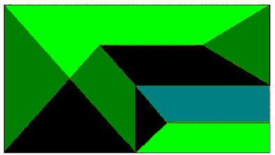
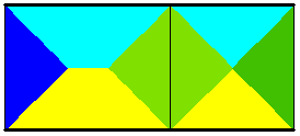
The goal of the trapezoidal and triangular method is to distribute the loads applied to a slab or to a cladding onto the bar elements supporting the slab or cladding, planar elements (panels) that are adjacent to a slab or cladding and supports with specified geometrical dimensions (use the Advanced option in the Support Definition dialog). A cladding is defined by an arbitrary contour that might have openings.

Dividing a loaded surface is based on the trapezoidal and triangular method of dividing a region, which is similar to constructing a projection of roof surfaces. A sum of the loads assigned to a support equals the area of a region assigned to a beam or edge or support, multiplied by a load value. If part of a projection of a divided shape extends off a bar, then this part is applied to the bar as a nodal, concentrated force.
For a support, a load from the area assigned to the node changes to a concentrated force.
Loads from claddings or panels using the trapezoidal and triangular load distribution method are distributed on all objects in the contour and plane of a cladding or panel:
- Bars in the cladding or panel plane - Robot automatically finds all bars in the plane and contour of a cladding or panel; it generates a linear, trapezoidal load on a bar
- Nodes of supporting bars - a load is distributed on nodes that belong to bars adjoining the cladding or panel plane (such as columns supporting the cladding or panel); it generates a nodal load. Distribution to nodes is ignored for one-way distribution
- Support nodes - a load is distributed on nodes that are assigned supports, however, the necessary condition is that a support is assigned advanced column properties, that is, the support dimensions needs to be specified. A contour of support dimensions determines an area of a rectangle; the load is distributed on this rectangle using the trapezoidal and triangular distribution; it generates a nodal load.
- Edges of supporting panels - a load is distributed on edges of panels that are adjacent to the plane of a cladding or panel (such as walls that support a cladding or slabs on which a load from the external panel wall is distributed); it generates a linear, trapezoidal load on the edge.
- Bars in the plane of a cladding (beam) and edges of supporting panels (walls) are equivalent objects on which the load is distributed
- A load applied to edges of walls is reduced to a trapezoidal load described by 2 points: an edge is divided by half; Robot calculates the sum of loads for to each half. Next, Robot calculates the average value of this load which becomes the extreme value of the trapezoidal load applied to the whole wall edge Loads applied to bars in the plane of a cladding or panel are calculated based on the internal division of a bar; thus analogous cases of distributing loads on walls and bars may differ in shape and values of components
- If a node belongs to a bar (beam) that lies in the plane of a cladding and the load has already been distributed on this bar (beam), it does not participate in the distribution on columns or supports
- For a load to be applied to a support, geometrical dimensions must be defined for this support (Support definition - Advanced dialog).
- Loads for claddings / panels are not distributed if elements of objects onto which the load is distributed overlap. This may occur in the following cases:
- Wall panels supporting the floor overlap.
- The mesh of wall panels is incoherent and uses kinematic constraints.
- A member that lies on the wall panel is not divided into calculation elements.
There are also maps of load distribution in the Robot. After selecting the Load distribution regions option in the Display dialog (Loads tab), the load distribution according to the trapezoidal and triangular method is displayed.
On all claddings calculated using the trapezoidal and triangular method, Robot displays maps showing to which supports individual regions belong. Drawing a map consists of applying colors to all the contours of surfaces in such a way that within one slab or cladding a border does not separate contours filled with the same color.

You can select objects that lie in the plane of a cladding (or of a panel for which the trapezoidal and triangular distribution is selected in a calculation model) and do not carry loads. In a real structure, these can be elements of roof bracing that do not carry the load transferred from the roofing. You can select these objects using either of the following ways:
- use options in the Inspector pane - in the object properties (bar or panel); for the Trapezoidal and triangular distribution option you can select Analyze (an object carries loads) or Ignore (an object does not carry loads)
- use the Trapezoidal and triangular method options dialog by selecting Geometry > Additional Attributes > Load Distribution - Options: for objects from the defined list you can click Analyze (objects carry loads) or Ignore (objects do not carry loads).