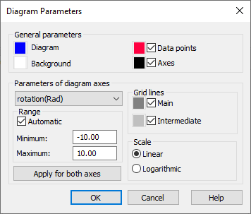
This option specifies the parameters for displaying the diagram at the top of the Definition of non-linear hinge model dialog or the Non-linear Model Definition dialog. Open the Diagram Parameters dialog by right-clicking in the diagram and from the shortcut menu, select Diagram parameters.

You can specify the following parameters in the field: In the General Parameters:
- Color of the diagram
- Background color of the diagram
- Color of the abscissa and ordinate axes (when selected, the axes are displayed on the diagram)
- Color of the points defining the diagram (when selected, the points defining the diagram are displayed).
In the Parameters of diagram axes field you can:
- Select the axis for which the parameters are defined (depending on the non-linear model type, the following axes are available: force, displacement, moment, and rotation).
- Select the range for each of the axes: the minimum and maximum value (when the Automatic option is selected, Robot selects the variability range for the variables). When you click Apply for both axes, the axis parameters refer to both axes in the diagram (that is, to force-displacement or moment-rotation axes).
- Specify whether grid lines (main and intermediate) are displayed in the diagram.
- Specify the scale (linear or logarithmic) are used to display values in the diagram.