Modifying the Geologic Hatch Pattern Styles in the Geotechnical Modeler
The Geotechnical Modeler installation comes pre-loaded with many hatch patterns for a variety of geology codes and types. These patterns are based on the AGS standard for soil classification however you can easily add or modify the available hatch patterns using the Hatch Style Editor.
Editing hatch pattern styles
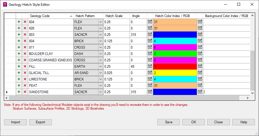
Click Geotechnical Modeler tab > Geotechnical Modeler panel >  Hatch Style Editor.
It is recommended that you open a drawing with a subsurface profile view already created so that any changes to the hatch patterns will be visible in the Civil 3D project. Open the Subsurface Profiles dialog box by selecting from Subsurface Profiles the ribbon.
Adding a geology hatch style
Select an existing style.
Click
 Add new hatch style.
An empty style is created above the selected style.
At the prompt, enter a new geology code name for the style.
Click OK
Select a Hatch Pattern from the drop down list.
Specify a Hatch Scale for the selected pattern.
Specify an Angle for the rotation of the selected pattern.
Click
 Select hatch color to specify the color of the hatch pattern.
Click
Select background color to specify the color behind the hatch pattern.Click OK to save and close the Hatch Style Editor.
Modifying an existing geology hatch style
- Select the geology code to be edited.
- Select a Hatch Pattern from the drop down list.
- Specify a Hatch Scale for the selected pattern.
- Specify an Angle for the rotation of the selected pattern.
- Click Select hatch color to specify the color of the hatch pattern.
- Click Select background color to specify the color behind the hatch pattern.
- Click OK to save and close the Hatch Style Editor.
Deleting an existing geology hatch style
Select the geology code to be deleted.
Click
 Delete selected hatch style.
The hatch style is removed from the list in the editor.
Importing a TOML style configuration file
- Click Import.
- In the Import Geology Hatch Styles dialog, navigate to the configuration file to be used.
- Select the file to be imported and click Open.
- Review the styles and their import status in the Import Geology Hatch Styles dialog.
- Specify how existing styles should be handled: erased, kept, or overwritten.
- Click Import.
Exporting a TOML style configuration file
- Click Export.
- In the Export Geology Hatch Styles dialog, navigate a directory where the file will be stored.
- Click Save..
About the TOML style configuration file
The hatch style configuration file (GeologyHatchStyle.config) is located in the following directory:
C:\ProgramData\Autodesk\C3D-GeoTechModeler-2023\StyleTemplateDrawingThis file can be opened in a text editor for manual editing.
Each line of the file represents a geology type and the parameters required to define the hatch pattern. An example of the hatch style configuration file content is shown below.
  [HatchStyles]
  101 = ["EARTH", "", "0.2500", "45.0000", "255,0,0", ""]
  102 = ["EARTH", "", "0.2500", "45.0000", "0,255,0", ""]
  205 = ["DASH", "", "0.2500", "0.0000", "0,0,255", ""]
  206 = ["DASH", "", "0.2500", "0.0000", "10,20,40", ""]
  212 = ["GOST_GLASS", "", "0.0050", "315.0000", "111", ""]
  213 = ["GOST_GLASS", "", "0.0050", "315.0000", "111", ""]
  220 = ["DASH", "", "0.2500", "0.0000", "3", ""]
  404 = ["AR-SAND", "", "0.0250", "0.0000", "2", ""]
  409 = ["AR-SAND", "", "0.0250", "0.0000", "2", ""]
  601 = ["FLEX", "", "0.2500", "0.0000", "31", ""]
  604 = ["FLEX", "", "0.2500", "0.0000", "31", ""]
  605 = ["FLEX", "", "0.2500", "0.0000", "31", ""]
  803 = ["SACNCR", "", "0.2500", "315.0000", "5", ""]
  804 = ["BRICK", "", "0.1250", "0.0000", "4", ""]
  811 = ["CROSS", "", "0.2500", "0.0000", "6", ""]
  "BOULDER CLAY" = ["DASH", "", "0.2500", "0.0000", "3", ""]
  "COARSE GRAINED IGNEUOS" = ["CROSS", "", "0.2500", "0.0000", "6", ""]
  FILL = ["EARTH", "", "0.2500", "45.0000", "1", ""]
  "GLACIAL TILL" = ["AR-SAND", "", "0.0250", "0.0000", "2", ""]
  LIMESTONE = ["BRICK", "", "0.1250", "0.0000", "4", ""]
  PEAT = ["FLEX", "", "0.2500", "0.0000", "31", ""]
  SANDSTONE = ["SACNCR", "", "0.2500", "315.0000", "5", ""]
Each line of the file must contain a text string for the geology code. This code will match up with the AGS standard or custom geology types included in your dataset. Please note that multiple word geology codes must be enclosed in quotes.
All parameters other than geology name are optional, however they must exist in the following order: GeologyName, HatchPattern, BlockName, Scale, Angle, and Color.
GeologyName is the name of the material that will be hatched.
HatchPattern is the AutoCAD hatch pattern that will be applied.
BlockName is the name of the block that will be used.
If the block size exceeds the area to be filled, it will be trimmed. If the block is smaller than the area to be filled, it will be arrayed and trimmed as required.
Scale is either the hatch pattern scale, or the amount the block will be scaled.
Angle is the angle that will be applied to the hatch pattern or how much the block will be rotated.
Color is the color applied to the hatch pattern expressed as an AutoCAD color index (1-255) or an RGB value (255,0,255).