Use this tab to create new grading criteria definitions.
If a criterion is currently used by one or more gradings, you cannot edit the values for Target or Projection.
Grading Method
- Target
-
Specifies the target method for the grading. Click one of the following:
-
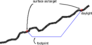
Surface: Specifies that the grading projection lines will be extended from the footprint until they match into a surface. You are prompted to select a target surface when you create a grading that uses these criteria.
Surface as grading target (section view)
-
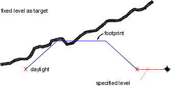
Level: Specifies that the grading projection lines will be extended from the footprint until they reach a specified level. Enter a positive or negative number in the Level field.
Level as grading target (section view)
-
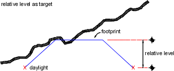
Relative Level: Specifies that the grading projection lines will be extended from the footprint until they reach a level (depth or height) relative to the footprint. Enter a positive or negative number in the Relative Level field.
Relative level as grading target (section view)
-
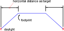
Distance: Specifies that the grading projection lines will be extended from the footprint until they match a specified horizontal distance. Enter a positive number in the Distance field.
Distance as grading target (section view)
-
Surface: Specifies that the grading projection lines will be extended from the footprint until they match into a surface. You are prompted to select a target surface when you create a grading that uses these criteria.
- Projection
-
Specifies the type of projection. Choices vary according to the target method.
- Cut/Fill Slope: Creates the grading by projecting a specific slope value towards a target that can occur both above and below the footprint, such as a surface or level target. Slope is always a positive value, as the type of slope determines whether it is going up or down from the footprint. Slope can be formatted as a slope value (run:rise or rise:run), or a gradient value (percent or decimal). Related parameter for surface target: see Search Order.
- Cut Slope: Creates the grading by projecting a specific slope value up to a target. Slopes can be formatted as a slope value (run:rise or rise:run), or a gradient value (percent or decimal).
- Fill Slope: Creates the grading by projecting a specific slope value down to a target. Slopes can be formatted as a slope value (run:rise or rise:run), or a gradient value (percent or decimal).
- Distance: Creates the grading with projection lines that extend a fixed horizontal distance from the footprint.
- Slope: Creates the grading by projecting to a specific (absolute) level using a specific slope value. Enter a positive or negative value. Slopes can be formatted as a slope value (run:rise or rise:run), or a gradient value (percent or decimal).
- Level: Creates the grading by projecting to a specific (absolute) level value.
- Relative Level: Creates the grading by projecting to a level value that is measured relative to the level of the footprint.
- Search Order
-
Specifies whether to search first for cut or fill slopes in cases where both would work. For example, where the target surface has a steep slope, both cut and fill slopes may intersect the surface.
- Cut First: Creates the grading by trying to grade up from the footprint. If no solution is found, it will gradient down.
- Fill First: Creates the grading by trying to grade down from the footprint. If no solution is found, it will gradient up.
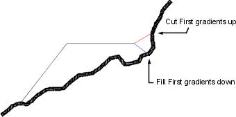
Different results achieved based on Cut First and Fill First settings (section view)
Note: Technically both of these situations are “fill”. However, Autodesk Civil 3D treats the up-slope direction as cut and the down-slope direction as fill.
(Cut Slope/Fill Slope/Distance/Level/Relative Level) Projection
- Format
-
Specifies how the slope should be represented. Click either Slope or Gradient in the list. The format can be further edited in the Grading Settings dialog box.
- Distance
-
Specifies the fixed distance from the footprint for the projection. Enter a value, or click
 to select a distance in the drawing area.
- Slope
-
Specifies the slope value. Enter a positive value in the form of run:rise or rise:run.
- Gradient
-
Specifies the gradient value. Enter a positive value as a decimal percent.
Conflict Resolution
- Interior Corner Overlap
-
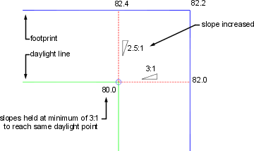
Specifies how interior corner projections are cleaned up when the footprint corner has different levels. This situation results in two possible daylight point levels. You can choose to average the slopes to reach the same point, or increase or decrease one of the slopes.
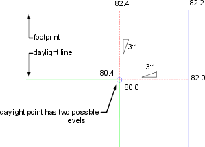
Corner level conflict (plan view)
-
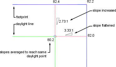
Use Average Slope: Averages the slopes to reach the same daylight point.
-
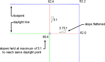
Hold Slope as Maximum: Holds the specified gradient or slope as the maximum and flattens out the slope projected from the footprint on one side.
-
Hold Slope as Minimum: Holds the specified gradient or slope as the minimum and increases the slope projected from the footprint on one side.
-
Use Average Slope: Averages the slopes to reach the same daylight point.