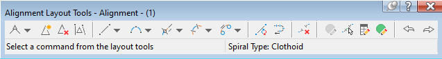
Use this toolbar to draw simple straight-straight lines, create constraint-based alignment geometry, and edit an alignment.
The name of the currently selected alignment is displayed at the top of the toolbar. When you click an icon, the current command is displayed at the bottom of the toolbar. The toolbar remains open when you grip edit the alignment or enter another command. The toolbar closes when you either delete the currently selected alignment or click the X button in the upper-right corner of the toolbar.
-
 Straight-Straight (No Curves)
 -
Adds a series of fixed straights between specified points.
-
 Straight-Straight (With Curves)
 -
Adds a series of fixed straights between specified points, with free curves automatically added at the intersection points.
-
 Curve And Transition Settings
 -
Specifies the curve parameters to use with the Straight-Straight With Curves command.
-
 Insert IP
 -
Breaks a fixed line into two adjacent fixed lines by creating an intersection point (IP) at a point that you specify.
-
 Delete IP
 -
Creates a single straight from two adjacent straights by removing their intersection point (IP).
-
 Break Apart IP
 -
Separates the intersection point (IP) where the endpoints of two fixed or floating straights meet.
-
 Convert AutoCAD Line And Arc
 -
Creates a fixed two-point line or three-point curve alignment element from an AutoCAD object.
An alignment sub-element that has been converted from an AutoCAD element may be added as a solved portion of the alignment geometry in either of two ways:
- Before the AutoCAD element is converted, it must be attached to an unattached end point of another solved sub-element in the alignment.
- After the AutoCAD element has been converted, it may be joined to the solved alignment geometry using the alignment layout tools.
-
 Reverse Sub-Element Direction
 -
Reverses the direction of a fixed, unconnected line or curve sub-element.
-
 Delete Sub-Element
 -
Deletes a specified alignment sub-element.
-
 Edit Best Fit Data For All Elements
 -
Displays a table of data that contains the original regression data for all alignment sub-elements that were created by best fit.
-
 Pick Sub-element
 -
Displays a selected sub-element's parameters for editing.
-
 Alignment Layout Parameters
 -
Displays a vertical table of numeric data about a single, selected alignment sub-element.
-
Alignment Elements
-
Displays a horizontal table of numeric data about multiple, selected alignment sub-elements.
-
 Undo
Undo -
Reverses the last Autodesk Civil 3D or AutoCAD command.
-
 Redo
Redo -
Reverses the last Undo command. Redo is limited to one operation.
Line Tools
Add constraint-based fixed, free, or floating straights to an alignment.
-
 Fixed Line (Two points)
 -
Adds a fixed line between two specified points.
-
 Fixed Line (From curve end, length)
 -
Adds a fixed line to and from the endpoint of an existing curve to another specified point. Tangency is not maintained if either element is edited.
-
 Fixed Line - Best Fit
 -
Adds the most probable fixed line through a series of Autodesk Civil 3D points, AutoCAD points, existing entities or clicks screen.
-
 Floating Straight (From curve, through point)
 -
Adds a floating straight from any point on an existing curve element through a specified point.
-
 Floating Straight (From curve end, length)
 -
Adds a floating straight with a specified length, to the end of a curve element. Tangency is maintained to the attached element end, regardless of how the element is edited.
-
 Floating Straight - Best Fit
 -
Adds the most probable floating straight from a point on an existing entity through a series of Autodesk Civil 3D points, AutoCAD points, existing entities or clicks screen. Tangency is maintained to the attached element, regardless of how the element is edited.
-
 Free Straight (Between two curves)
 -
Adds a free straight between two existing curves.
Curve Tools
Add constraint-based fixed, free, or floating curves to an alignment.
-
 Fixed Curve (Three points)
 -
Adds a fixed curve through three points.
-
 Fixed Curve (Two points and direction at first point)
 -
Adds a fixed curve that is defined by specified start and end points and a direction at the start point.
-
 Fixed Curve (Two points and direction at second point)
 -
Adds a fixed curve that is defined by specified start and end points and a direction at the end point.
-
 Fixed Curve (Two points and radius)
 -
Adds a fixed curve that is defined by specified radius, direction, and start and end points.
-
 Fixed Curve (From element end, through point)
 -
Adds a fixed curve from the end of an existing element to a specified end point.
-
 Fixed Curve (Center point and radius)
 -
Adds a full, fixed circle that is defined by a specified center point, direction, and radius.
-
 Fixed Curve (Center point and through point)
 -
Adds a full, fixed circle that is defined by a specified center point, direction, and pass-through point.
-
 Fixed Curve (Through point, direction at point and radius)
 -
Adds a full, fixed circle that is defined by a specified pass-through point, direction at the pass-through point, curve direction, and radius.
-
 Fixed Curve - Best Fit
 -
Adds the most probable fixed curve through a series of Autodesk Civil 3D points, AutoCAD points, existing entities or clicks screen.
-
 Floating Curve (From element, radius, through point)
 -
Adds a floating curve, which is defined by a specified radius and angle range, from an existing element to a specified end point.
-
 Floating Curve (From element end, through point)
 -
Adds a floating curve from the end of an existing element to a specified pass-through point.
-
 Floating Curve (From element, through point, direction at point)
 -
Adds a floating curve from an existing element to a specified pass-through point.
-
 Floating Curve (From element end, radius, length)
 -
Adds a floating curve, which is defined by a specified direction, radius, and length, to the end of an existing element.
-
 Floating Curve - Best Fit
 -
Adds the most probable floating curve from an existing entity through a series of Autodesk Civil 3D points, AutoCAD points, existing entities or clicks screen. Tangency is maintained to the attached element, regardless of how the element is edited.
-
 Free Curve Fillet (Between two elements, radius)
 -
Adds a free curve, which is defined by a specified angle range and radius, between two elements.
-
 Free Curve Fillet (Between two elements, through point)
 -
Adds a free curve, with a specified pass-through point, between two elements.
-
 Free Curve - Best Fit
 -
Adds the most probable free curve between two existing entities and through a series of Autodesk Civil 3D points, AutoCAD points, existing entities or clicks screen. Tangency is maintained to the attached elements, regardless of how the elements are edited.
Lines with Transition Tools
-
 Floating Straight With Transition (From curve, through point)
 -
Adds a floating transition-line group, which is defined by a specified pass-through point, to a curve.
-
 Floating Straight With Transition (From curve end, length)
 -
Adds a floating transition-line group, which is defined by the line length, to a curve.
Curves with Transition Tools
-
 Floating Curve with Transition (From Element End, radius, length)
 -
Adds a floating transition-curve group, which is defined by a specified radius and pass-through point, to a line.
-
 Floating Curve with Transition (From element, radius, through point)
 -
Adds a floating transition-curve group, which is defined by a specified radius and length, to a curve.
-
 Floating Reverse Curve with Transitions (From curve, radius, through point)
 -
Adds a floating reverse transition-transition-curve group, which is defined by a specified radius and pass-through point, to a curve.
-
 Floating Reverse Curve with Transitions (From curve, two points)
 -
Adds a floating reverse transition-transition-curve group, which is defined by two specified pass-through points, to an existing curve.
-
 Free Transition-Curve-Transition (Between two elements)
 -
Adds a free transition-curve-transition group between
- Two straights, creating a simple transition.
- A straight and a curve, creating a compound transition at one end and a simple transition at the other end.
- Two curves, creating two compound transitions at each end.
-
 Free Compound Transition-Curve-Transition-Curve-Transition (Between two straights)
 -
Adds a free compound transition-curve-transition-curve-transition group between two straights. You can specify a zero length for any of the three transitions.
-
 Free Reverse Transition-Curve-Transition-Transition-Curve-Transition (Between two straights)
 -
Adds a free reverse transition-curve-transition-transition-curve-transition group between two straights.
Transition Tools
-
 Fixed Transition
 -
Adds a fixed transition, which is defined by a specified radius and length, to the end of a line or curve.
-
 Free Transition (Between two elements)
 -
Adds a free, compound transition between two curves with different radii.
-
 Free Compound Transition-Transition (Between two curves)
 -
Adds a free compound transition-transition group between two curves.
-
 Free Reverse Transition-Transition (Between two curves)
 -
Adds a free reverse transition-transition group between two curves.
-
 Free Compound Transition-Transition (Between two straights)
 -
Adds a free compound transition-transition between two straights.
-
 Free Compound Transition-Line-Transition (Between two curves, transition lengths)
 -
Adds a free compound transition-line-transition group, which is defined by specified transition lengths, between two curves.
-
 Free Reverse Transition-Line-Transition (Between two curves, transition lengths)
 -
Adds a free reverse transition-line-transition group, which is defined by specified transition lengths, between two curves.
-
Free Compound Transition-Line-Transition (Between two curves, line length)
-
Adds a free compound transition-line-transition group, which is defined by a specified line length, between two curves.
-
 Free Reverse Transition-Line-Transition (Between two curves, line length)
 -
Adds a free reverse transition-line-transition, which is defined by a specified line length, between two curves.