Use this dialog box to control which components are referenced into a drawing by default from an attached reference template.
By default, only the components that are selected when you set up the reference template will be referenced into the host drawings. When you attach a reference template, you can review which components were selected and you can adjust the selection as needed.
Use the tabs in the left pane to view and select components to reference. Use the icons to expand or collapse the categories on the tabs and to select all components or clear all selections. When you select a component in the left pane, the properties of that component are displayed in the right pane of the dialog box. Those properties are read-only and cannot be edited.
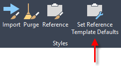
Accessing the Set Reference Template Defaults dialog box
This dialogue box is displayed when you select the Set Reference Template Defaults command on the Manage tab. The Set Reference Template Defaults command is available on the ribbon only when you are working in a DWT file.
You can also access this dialog box from the Template Options dialogue box by clicking Set Defaults.
Icons
 Expand All Categories
- Expands all categories on the current tab.
 Collapse All Categories
- Collapses all open categories on the current tab.
-
 Tick Boxes
 - Selects or clears components on the current tab.
The check boxes have a tri-state display. If only some components are selected, the tick box is shaded
 . If all components are selected, the tick box is selected
  . If all components are cleared, the tick box is cleared
  .
.
Some tick boxes cannot be cleared if other components are dependant on them. If a component is shown in grey, it is referenced by another component that is currently selected and the tick box cannot be cleared.
You can move your cursor over the component to display a tooltip that lists where the component is referenced.
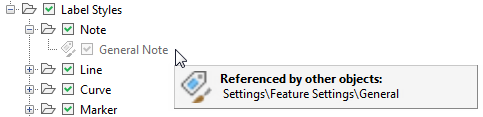
In this example, the General feature settings reference the General Note style, so the tick box for General Note cannot currently be cleared.
Styles
Use the Styles tab to select the following Autodesk Civil 3D styles to reference.
- Object styles
- Label styles
- Table styles
- Quantity takeoff criteria
- Pipe and structure rule sets
-
Pipe network and pressure network parts lists
Note: For an imported parts list to work correctly in the drawing it is imported into, the part catalogue that was used to generate that parts list must be set as the current part catalogue. Use the Set Pipe Network Catalogue command or the Set Pressure Network Catalogue command to specify the current part catalogue.
All expressions and alignment and profile design check sets are referenced by default.
 . When you move your cursor over the component name, a tooltip is displayed that contains information about the component and the reference template.
Settings
Use the Settings tab to select the following Autodesk Civil 3D settings to reference.
- The following drawing settings:
- Object layers
- Abbreviations
- Ambient settings
- Label style default settings
- Feature settings
Layers
Use the Layers tab to select the AutoCAD layers to reference.
You can use the AeccRefTemplateAutoUpdate system variable to prevent layer properties in host drawings from being overwritten by reference templates. For more information, see To Work With Reference Templates.
Other Resources
Use the Other Resources tab to select the AutoCAD blocks, text styles and line types to reference.
Property Sets
Use the Property Sets tab to select the Autodesk Civil 3D property sets to reference.