Create associated longitudinal section views to display a centerline profile and related offset profiles in vertically arranged profile views. Each profile view in the series or stack is an independent profile view object. Each profile view object appears in Prospector, and you can modify the properties of each object independently.
![]() Tutorial Exercise: Creating Stacked Profile Views
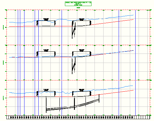
Tutorial Exercise: Creating Stacked Profile Views
-
Click
 Find.
Find.
OR
Click
Find.
- In the Create Profile View wizard, on the General page, select the Show Offset Profiles By Vertically Stacking Profile Views check box.
The link to the Associated Longitudinal Section page is displayed on the left.
- On the General page, specify the alignment name and profile view name and description. Note: Click Create Profile Views at any time to accept the current settings.
- On the Station Range page, specify the starting and ending stations.
- On the Profile View Height page, specify the profile view height and any split long section options, including split stations and styles for individual stations. Note: If the profile level values are relatively consistent, under the Profile View Datum By option, select Mean Level. The Mean Level option vertically centers the profile line in the profile view, creating equal space above and below the profile line.
- On the Associated Longitudinal Section page, specify the number of associated longitudinal section views, gap between the views, and the profile view style to use in the top, middle, and bottom views. Note: The top and bottom profile views can use separate styles. All profile views between the top and bottom must be created with the same style.
- On the Profile Display Options page, select a profile view from the Select Stacked View To Specify Options For list.
- In the Specify Profile Display Options table, specify the profiles to be drawn as well as their styles, labels, and layers.
- Repeat steps 7 and 8 for each profile view in the stack.
- On the Pipe/Pressure Network page, specify which pipe networks or parts will be drawn in each associated longitudinal section view. Follow the workflow described in steps 7 through 9 to specify the options for each associated longitudinal section view.
- On the Data Boxes page, specify the data box sets and their properties.
The data boxes will appear at the top or bottom of the stack.
- For multiple,associated longitudinal section views, on the Multiple Plot Options page, specify how the multiple profile views will be laid out.
- Click Create Profile Views.
- In the drawing window, click a location for the origin of the stack of profile views. Note: The profile view grid origin is determined by the Start Corner setting on the Multiple Plot Options page.