You can connect pipes to objects created by other programs including AutoCAD MEP and AutoCAD Plant 3D using an Autodesk Connector (ACP) object. You can also create an ACP object to allow other programs to connect to Autodesk Civil 3D pipe networks.
You can connect to ACP objects that are attached as an external reference (Xref).
ACP connector objects do not require Object Enablers from the program that created them to be installed.
To create an ACP connector
- Click Insert tab
 Connection Point panel
Insert Find.
Connection Point panel
Insert Find.
- In the drawing area, select the object to add the connection point to.
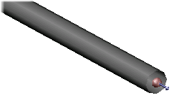
- Specify an insertion point on the object. You can use the CEN object snap, for example, to snap to the center of a pipe.
Tip: Change to a 3D view so that you can more easily snap to the center of the pipe.
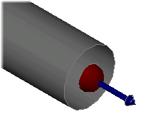
- Specify two direction points.
Tip: By defining the two direction points by snapping to the center of the pipe start point and then to the center of the pipe end point (where you are attaching the connection point), the direction of the connection point will match the direction of the pipe.
- Specify whether to create engineering data. Adding engineering data pre-populates some properties that you can then assign values to when you edit the connection point.
An ACP object is created.
To connect to an ACP connector
- In the Pipe Network Feature Settings, under Pipe Network Defaults, ensure that Use 3D Location During Pipe Network Layout is set to Yes.
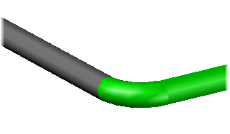
- Create or edit a pipe network. A marker appears when you hover over the ACP connector. Click on the ACP connector to make a connection.
- Continue creating or editing the pipe network.