Surveyors locate existing features on the ground using systems, such as a total station or a GPS unit, that are configured with data collectors. For each surveyed point, the surveyor assigns a field code that describes the point feature or line feature and that is then saved in the data collector. Line features contain a line command code that indicates whether the line is a beginning, a continuation, an end, a curve segment, or a line segment. In Autodesk Civil 3D, the syntax of the field code corresponds to a previously defined linework code set. The correspondence between the field codes and the linework code set allows for the following:
- Automatic assignment of COGO point properties such as Layer, Symbol, and Label when inserted into the drawing
- Automatic assignment of line feature properties, such as Layer, Color, Linetype, and Lineweight when inserted into the drawing
- Line connectivity between the COGO points
An example of a field code is EP1 B, where:
- EP = the standard abbreviation that a company uses to represent an edge of pavement
- 1 = the first edge of pavement that is located
- B = the code in the linework code set to begin a figure Note: NOTE: When you import survey data, you can omit the Begin code if the feature name matches a figure prefix that is defined in the current figure prefix database. If the feature name does not match a figure prefix, you must specify a Begin code.
Field codes are associated with both the figure prefix database and the description keys in the current drawing. If EP has been defined in the figure prefix database, then EP1 matches EP and is assigned the properties of the EP figure prefix, such as layer, figure style, breakline. If the survey point with the description EP1 B is placed in a drawing that has a description key of EP*, then EP1 B matches description key EP* and is assigned the point properties defined in the EP* description key, such layer, point style, point label style.
The following table lists examples of features coded in the field and the field code assigned to the feature, and the description keys and Figure prefixes created in Autodesk Civil 3D to support the field codes:
| Feature | Field Code | Description Key | Figure Prefix |
|---|---|---|---|
| Edge of pavement | EP<ID> | EP* | EP |
| Utility Pole | UP<ID> | UP* | |
| Fence Line | FCE<ID> | FCE* | FCE |
| Centerline | CL<ID> | CL* | CL |
| Ditch Line | DL<ID> | DL* | DL |
| Edge of Gravel | EG<ID> | EG* | EG |
| Sewer Manhole | SMH<ID> | SMH* | |
| Storm Manhole | DMH<ID> | DMH<ID> | |
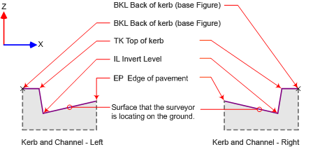
The following illustration shows an example of feature definitions:
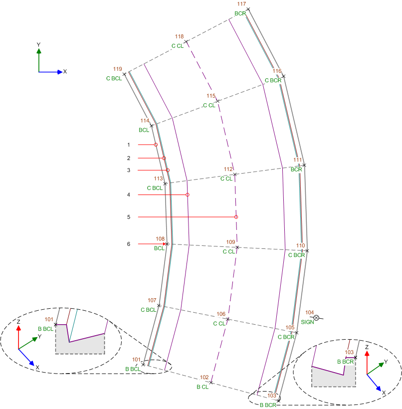
The following illustration shows these feature codes:
- 1: BK (back of kerb)
- 2: TC (top of curve)
- 3: IL (invert level)
- 4: EP (edge of pavement)
- 5: CL (centerline of existing carriageway)
- 6: Point located in the field by a surveyor