Create AutoCAD blocks and use them to represent each view of the multi-view block definition.
Creating individual blocks for multi-view block definition
- Draw the views you need for a specific display representation:
- To create views for the front and back directions, draw them on the XZ plane.
- To create views for the left and right directions, draw them on the YZ plane.
- To create views for the top and bottom directions, draw them on the XY plane.
- Specify additional insertion points on the defpoints layer in the AutoCAD point command, if necessary. Note: The points added to view blocks are cumulative. For example, if you add one point to a view block used for the top view and two points to the view block used for the model view, you have a total of four points to cycle through. The fourth point is the regular basepoint defined during the creation of the block.
- Make sure the current coordinate system is the world coordinate system before making blocks from these individual views.
For more information about coordinate systems, see the AutoCAD Help.
- Define each view as a block, and specify the location of the insertion base point as you define each block.
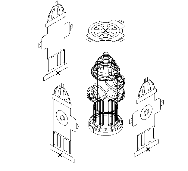
For example, if you specify the insertion base point of the model view block as the dead center of the top side, the front, back, left, and right view blocks will all have an insertion base point at the midpoint of the bottom edge. In the following illustration, the insertion points for the top, front, and side view blocks are indicated by an “X”. For more information about blocks, see the AutoCAD Help.
Tip: It is helpful to have a naming convention as you save your views as blocks. For example, name the plan view block hydrant-p, and name the right view block hydrant-r.