Create layout profiles to represent designed levels along an alignment.
You typically draw a layout profile on the grid of a profile view, using the surface profile as a guide.
A profile view grid must exist in the drawing to draw layout profiles. Create curves and straights by freehand sketching or by entering numeric values.
You can create a layout profile with straights, and then optionally add curves at the vertical intersection points (VIP).
You can create a profile from an external ASCII file that contains a series of chainages along an alignment, the level of each chainage, and optionally, the length of curve at the chainage.
Curve attributes are set by the Curve Settings command. These curves maintain tangency when edited.
Several methods are available for drawing a layout profile:
- Use the
 Draw Straights command to specify vertical intersection points (VIPs) for a series of straight straights. Later you can add free curves with specific parameters between the straights.
- Use the
 Draw Straights With Curves command to specify VIPs for the tangents, automatically creating curves between the straights using the parameters you specify in the Vertical Curve Settings dialog box.
- Use the constraint-based profile design commands to create a profile one sub-element at a time.
When you are prompted for point locations, you can use the Transparent Commands to specify points in the profile.
To create a more detailed design using a specific parameter or other constraints, or to create curves without first creating straights, use the constraint-based tools included on the Profile Layout Tools toolbar.
The criteria-based design feature allows a layout profile to be validated against local design standards. You can select a design criteria file and/or a design check set using either the Create Profile - Draw New dialog box when you create the layout profile, or the Design Criteria tab of the Profile Properties dialog box after it has been created.
Drawing layout profiles
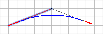
You can use the Draw Straights and Draw Straights With Curves commands to create a quick layout of the profile. The lines and curves you create maintain tangency when you edit them. Using these commands, you can draw profiles from left-to-right or right-to-left.
Profile entities drawn from left-to-right:
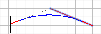
Profile entities drawn from right-to-left:
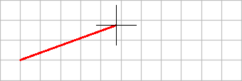
Draw Straights command
Use this command to create a quick layout of the profile. Specify straight start and end points (1 through 4), then add curves at the intersection points as necessary. The straights are fixed, so you can edit them and they always maintain tangency.
Draw Straights With Curves command
Use this command to create a quick layout of the profile, with curves automatically created at intersection points. Specify straight start and end points (1 through 4), and curves are created at the intersection points (2, 3) based on the values you enter in the Curve Settings dialog box. You can edit the straights and curves and they always maintain tangency.