You can create a junction using the Create Junction wizard.
Before creating a junction object, you must have two alignments that intersect. If you want to create a three-dimensional junction model, you must also have profiles associated with the intersecting alignments. Once you have the desired prerequisites, then you can create the junction object using the Create Junction wizard.
Creating a Simple 2D Junction
When the junction object is created, a variety of tasks can be performed automatically, including the following:
- creating offset alignments for the roads included in the junction
- creating corner radius alignments (corner radii) in the junction area
- creating profiles for the offset alignments and corner radius alignments that were created when the junction was created
Note: An exception to this is that if you set pre-defined static alignments as offsets, it is expected that you will specify profiles too. No dynamic offset profiles will be created.
- creating new corridor regions for the existing corridors in the junction area, or creating new corridor objects in the junction area
- locking the profile levels of the secondary road to the main (primary) road profile
Some of these tasks are optional. They depend on options selected in the Create Junction wizard.
The simplest way to create a basic two-dimensional junction object is to start with two alignments that intersect each other only once. You cannot use the Create Junction wizard if the alignments do not intersect.
If your drawing has two intersecting alignments that meet this criteria, you can create a basic 2D junction object using the Create Junction wizard. Simply start the command, follow the prompts, and accept the default choices on the wizard dialog boxes.
Creating a 3D Junction with Corridor Objects, Alignments, and Profiles
To create a 3D Junction that includes a corridor, you will need to first create the road geometry (road centerline alignments and profiles) and existing ground surface in your drawing. Once these components exist in the drawing, you can proceed with using the Create Junction wizard. The wizard prompts you to select the location in the drawing where the two road centerline alignments intersect.
You can start with the following data combinations:
- two intersecting centerline alignments
- two intersecting centerline alignments with one or more road edge offset alignments and or their profiles
You can have profiles defined already, or not. However, if profiles are not available, then features that are associated with 3D modeling will not be available on the wizard. For example, if you begin creating a junction object with no profiles, then the following wizard options will not be available for selection: creating offset alignment and corner radius profiles, as well as the ability to create a new corridor, or to add to an existing corridor in the junction area.
With any of the scenarios just described, you can start the Create Junction command, select the point where the centerline alignments intersect, and proceed with creating a junction using the Create Junction wizard.
Junction Road Priority
When you create a junction object, a Priority value is assigned to the main (primary) and secondary (side) road alignments . The following table lists the value of the Priority property:
| Road (alignment) | Priority |
|---|---|
| Main (primary) road alignment | 1 |
| Side road alignment | 2 |
If you are creating a T-shaped (3-way) junction, then the alignment that passes through the junction is automatically specified as the primary road (main road). In this situation, the Priority is automatically set to a value of 1 for that alignment, and you are not prompted to specify which road is the primary road because this happens automatically.
You cannot change the priority of a road in a junction after it has been created. However, if you want to change the priority of the alignments during the junction creation, you can do so from the Geometry Details page of the Create Junction wizard.
It is also important to note that typically, the side road (or lower priority) profile is automatically locked at the junction location to the level of the main road (higher priority) main road. The profile of the main road is not modified.
Junction Grading Options
The Junction Corridor Type property identifies the type of grading that will be applied to roads in a junction object: Primary Road Crown Maintained or All Crowns Maintained. You must specify this type when you create the junction, on the General page of the Create Junction wizard.
For existing junctions, the junction corridor type is displayed on the Junction Details tab of the Junction Properties dialog box, in the Junction Quadrants section. You can set the creation default for this option in the Edit Command Settings – CreateIntersection dialog box.
Once the junction is created, you cannot change the value of the Junction Corridor Type property. If you do want to change this option after the junction object is created, you must delete the junction object, and create a new one with the desired Junction Corridor Type.
Primary Road Crown Maintained
In this type of junction, the crown of the primary road is maintained, while the crown (profile) of the side road is adjusted to match the edge of the primary road and the junction point. The crown (profile and edges) of the primary road are not affected.
The following conceptual graphic is displayed on the wizard dialog when you select this option:
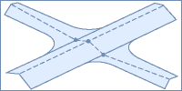
This represents how the grading occurs for the junction object.
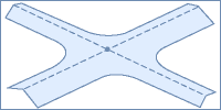
All Crowns Maintained
In this type of junction, the profile of the side road is adjusted to match the main road level at the junction point. The main road profile is not affected. The edges are blended together along the corner radius (via the corner radius profiles).
The following conceptual graphic is displayed on the wizard dialog when you select this option:
Junction Object Considerations
It is important to understand the following before you begin creating junctions:
- Using the Create Junction wizard, you can create a junction object that contains up to four quadrants.
- If the default junction assembly mapping and target assignments does not meet your design requirements, you can create the junction using these components, and then edit the junction regions manually to satisfy your design requirements.
- If you create a junction, and then manually edit the junction corridor regions, those changes will be overwritten if the junction is regenerated (by clicking Recreate Corridor Regions on the Junction tab) or by rebuilding the junction.
- When creating a junction, targeting (both horizontally and vertically) is done automatically. If you want to change targets, you must manually modify the junction corridor region(s) using the Corridor Properties dialog box.
- Typically, when a junction object is created, the following objects are automatically added to the current drawing: junction object, corridor(s), assemblies, subassemblies, offset alignments, and corner radius alignments. However, assemblies, subassemblies, corridors, and profiles are only added if the appropriate options are selected.