Use the Part Builder Autolayout commands to define the placement point where a part is inserted into a drawing.
- On the Part Builder toolbar, click Options.
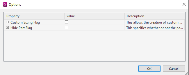
The Options dialog box is displayed.
- Make sure the check box in the Value column for the Custom Sizing Flag property is unchecked, and that the Hide Part Flag property is checked, then click OK.
In the part browser, Autolayout Data is added to Modeling, and trim length points are displayed on the model in the modeling area.
- Change the model view to plan view. On the View menu, click 3D Views
 Plan View World UCS.
 - In the part browser, expand Autolayout Data, right-click Layout Data and click Add Trim Length. Note: To ensure components are trimmed correctly when placing a part into a drawing, you must define trim lengths for the part in a specific order—left to right, then bottom to top.
You are prompted to select the start and end of the trim length. Repeat this for the three trim lengths required for auto layout of the part.
- Define the first trim length.
For the start of trim length 1, select the point at the center of the part. For the end of trim length 2, select the point at the left end of the part.
- Define the second trim length.
For the start of trim length 2, select the point at the center of the part. For the end of trim length 2, select the point at the right end of the part.
- Define the third trim length.
For the start of trim length 3, select the point at the top of the branch (the center of the part). For the end of trim length 3, select the point at the bottom of the branch.
Trim length lines are displayed between the selected points.
- Define the first trim length.
- In the part browser, right-click Layout Data and click Select Placement Point.
You are prompted to select a point on your model. This point is the location at which connecting segments would intersect if they were extended along their logical paths. The placement point is used as the insertion point for the part when it is added to a drawing during autolayout.
- Select the trim length point at the center of the part.
A placement point is displayed at the selected location.