Use the Layout tab to create a direction arrow component for a label style.
From the Create Component list ![]() , click
, click ![]() to create a new direction arrow component.
to create a new direction arrow component.
General
- Name
-
Specifies the name of the direction arrow component.
The default name, such as “Direction Arrow.1,” is the component name with a numeric increment. If the arrow component exists in a parent label style, then the name cannot be edited.
- Visibility
-
Specifies whether the direction arrow component is visible in the label style.
- Used In
-
Specifies whether the component is visible in tag mode, label mode, or both. Select a mode on the General tab in the Label Style Composer.
- Label Mode: Displays the direction arrow component when Display Mode is set to Label.
- Tag Mode: Displays the direction arrow component when Display Mode is set to Tag.
- Label and Tag Modes: Displays the direction arrow component regardless of the display mode setting.
Note: If a label style type does not support tables, then this control is not available. - Anchor Component
-
Specifies a reference object for positioning the direction arrow component. You can select <Feature> (which is the object being labeled) or another existing label component.
- Anchor Point
-
Specifies the location on the Anchor Component where the direction arrow component is attached.
- When <Feature> is the Anchor Component, Label Location is the only option available. This option places the anchor point at the point where the label is attached to the object being labeled.
- When the Anchor Component is another label component, you have a choice of anchor points depending on whether the anchor is a text, block, tick, line, or direction arrow component.
- Span Outside Segments
-
Specifies whether the label style component should span outside segments.
Note: This setting applies to plot line and curve label styles only).- True: Labels the outer boundary of plots, rather than the individual plot segments. For example, if four plots share an outer boundary, use this option to label the combined outer boundary.
- False: Labels individual plot segments.
Direction Arrow
- Arrow Head Style
-
Specifies the arrow head style. Select an arrow head style from the list.
Note: Select None to create a direction arrow without an arrow head. - Arrow Head Size
-
Specifies the size of the arrow head in plot units.
Note: A value of zero creates a direction arrow without an arrow head.Note: The direction arrow length must be at least twice that of the specified arrow head size. If not, the arrow head is not displayed. For example, if you specify an arrow head size of 0.2, the arrow length must be at least 0.4. This behavior is similar to AutoCAD leaders.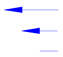
Arrow head is not displayed when arrow length is decreased
- Fixed Length
-
Specifies whether the arrow length is controlled by the Length setting or by the length of the object being labeled.
- True: Uses the Length setting.
- False: Draws the length of the direction arrow to match the length of the object being labeled.
- Length
-
Specifies the overall length of the direction arrow, including the arrow head.
The Length setting is unavailable when the Fixed Length property is set to False.
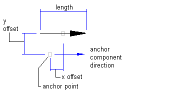
- X Offset
-
Specifies the offset distance between the mid-point of the direction arrow and the anchor component in the X direction.
- Y Offset
-
Specifies the offset in the Y direction.
The following illustration shows X and Y offsets for a direction arrow: