Use this tab to specify the curve group type to create, to define curve and spiral parameters and to define offset and overlap parameters for the connected alignment.
- Curve Group Type
- Specifies the curve group type to create.
- Circular Fillet
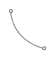
- Transition-Curve-Transition
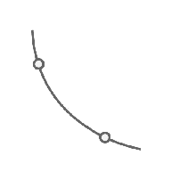
- Reverse Spiral-Spiral-Curve-Spiral
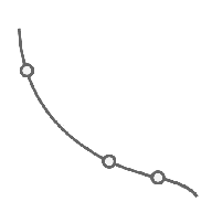
- Reverse Spiral-Curve-Spiral-Spiral
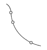
- Reverse Spiral-Spiral-Curve-Spiral-Spiral
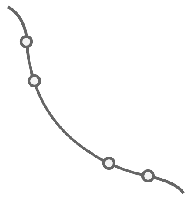
- Three Centred Arc
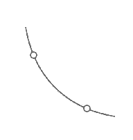
- Circular Fillet
- Curve Radius
-
Specifies the curve radius for the connected alignment.
Note: You can specify default values for the curve radius and connection overlap in the CreateAlignmentConnected command settings. - Spiral Parameters/Curve Parameters
- Displays the parameters for the curve group type. Click the browse button
 to open the Spiral Settings dialog box or the Three Centred Arc dialog box.
 - Degree of Curvature
- Specifies whether the degree of curvature of the connected alignment will be less than or greater than 180 degrees.
Note: Circular Fillet and Three Centred Arc curve group types do not support solutions that are greater than 180 degrees.
- Offset In/Offset Out
- Specifies the offset values for the connected alignment. The values are measured from the existing alignments.
- Connection Overlap In/Connection Overlap Out
-
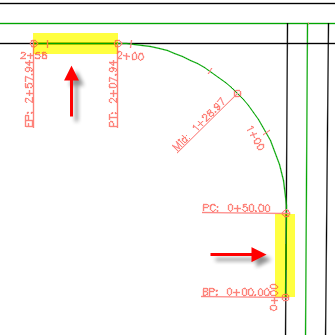
Specifies how much overlap to insert at the ends of the connected alignment. This value is used so that a portion of the ends of the new alignment overlaps onto the existing alignments where they join.
The following example shows the effect of a 50 foot overlap. The connected alignment is overlapped onto the existing alignments for 50 feet.
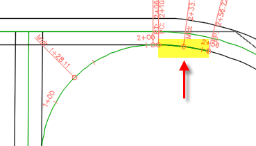
If the overlap occurs on a curve, the overlapping portion of the connected alignment will follow the curve.
- Preview
- Displays a preview of the connected alignment in the drawing. If a connected alignment cannot be created based on the specified parameters, a dialog box will be displayed with options you can use to create an auto-fit alignment, to return to the Create Connected Alignment dialogue box to specify different parameters or to cancel the command.