Set properties of profile views either from the Toolspace Prospector tab, or from the drawing window.
You can change the chainage range, grid, displayed profiles and annotation of objects in the profile view.
By specifying properties, you control the content and format of a profile view. Profile view properties are organized on several tabs of the Profile View Properties dialog box: information, chainages, levels, profiles, bands, hatch, projections and pipe networks. The tabs for projections and pipe networks appear if the profile view includes these objects.
Set these properties when you create a profile view. At any time, you can use the Profile View Properties dialog box to make changes.
Information Tab
View or edit the profile view name, description, and object style.
Stations Tab
Set the range of chainages displayed in the profile view.
Levels Tab
Set the range of levels displayed in the profile view. If the profile view is split, you can use this tab to specify the chainages and styles for the split segments.
Profiles Tab
Specify which profiles to display in the profile view and whether the view is clipped to the extents of a specific profile. You can edit the description, change the update mode (dynamic or static), layer, and style for each profile in the current view. You can also specify whether to split the profile view, which reduces its vertical size.
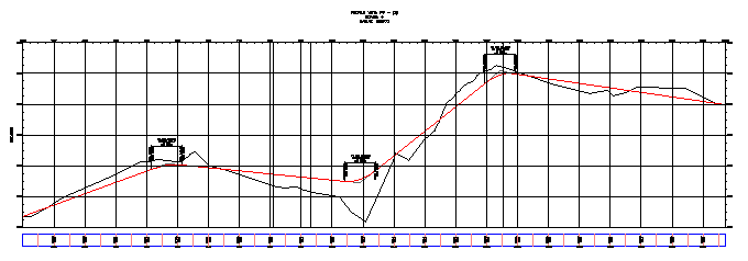
Profile view without split
The sample profile view before splitting shows a level range of 60 feet.
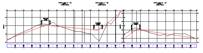
Profile view with split
The split long section view is more compact, with a level range of about 38 feet. At the split chainage, a separate level scale is provided for each part of the profile view.
Bands Tab
Specify which data boxes to include in the profile view and whether they are placed along the top or bottom of the grid. The following data box types are available for displaying profile data: profile data, vertical geometry, horizontal geometry, superelevation for a specified horizontal alignment, long section and pipe network data.
Hatch Tab
Specify the style and location of hatching between surfaces, which shows cut regions and fill regions in the vertical design.
Pipe Networks Tab
Specify which pipes or structures to display in the profile view as well as their styles, style overrides and layer placement. The Pipe Networks tab is displayed only when there is one or more pipe networks in the drawing.
Projections Tab
Specify objects from plan view to project into the profile view, including AutoCAD objects and Autodesk Civil 3D objects. You can also specify the object display styles, level options, and level values. The Projections tab is displayed only when projected objects exist in the profile view.
Crossings Tab
Specify objects in plan view to show as crossing objects in the profile view, including alignments, profiles, feature lines, survey figures and 3D polylines. You can also specify the marker styles, label styles, level options and level values. The Crossings tab is displayed only when crossing objects exist in the profile view.