Use corridor sections to examine the assemblies that make up a corridor model, as well as the surrounding civil objects, such as surfaces and pipe networks.
Sample lines are generated along a corridor's baseline alignment. Sections and section views are then created to visualise the corridor and surrounding terrain up to a specified swath width on either side of the baseline. The sections can also be used to calculate corridor material volumes.
If a sample line intersects with assemblies that are included on another baseline, then they may also be included in volume calculations that are done on the sample line group.
Positioning Sample Lines on a Corridor
Depending on the angle of the sample line relative to the parent baseline, a corridor section can be displayed in either of two ways.
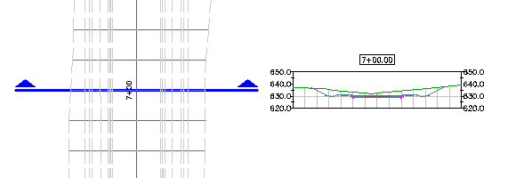
Perpendicular to a Corridor Baseline
When the sample line is perpendicular to the parent baseline, the section reproduces the corridor assembly that is inserted the chainage at which the sample line intersects with the baseline.
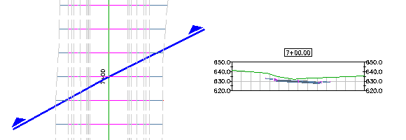
At an Angle to a Corridor Baseline
When the sample line is not perpendicular to the parent baseline, the section samples the corridor model, creates a solid of the subassemblies that the sample line crosses, identifies features (such as links, points, and shapes) on the sliced solid, and then slices the solid to produce a sectional representation.
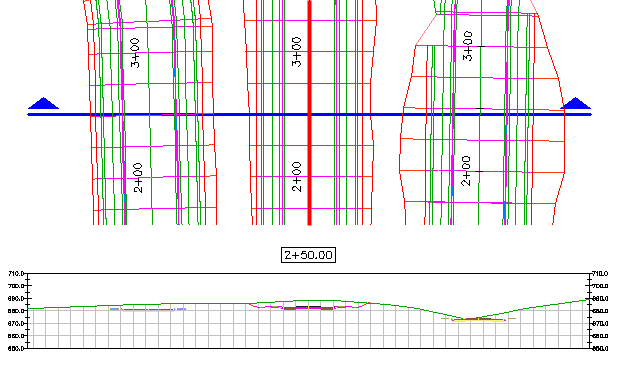
Sampling Multiple Corridor Baselines
A corridor section may sample multiple corridor baselines. A corridor section that samples multiple baselines is created in two steps:
- On the parent baseline (to which the sample line is attached), the corridor assembly that is inserted at the nearest chainage along the baseline is reproduced.
- On other subassemblies that intersect the sample line, the sample line samples each subassembly, creates a solid of the subassemblies, slices the solid to produce a sectional representation, and then identifies features (such as links, points, and shapes) on the sliced solid.
Note: On sampled assemblies that are not attached to the parent baseline, daylight links are reproduced only if the sample line is perpendicular to the assembly baseline. To view complete daylighting in a multiple baseline section, create top surfaces of all the sampled corridors, and then sample the corridor top surfaces.
You can sample cross sections of complex or multiple corridors, such as junctions, roundabouts, cul-de-sacs, off ramps and access roads. In the following images, the corridors consist of multiple baselines. Using the sample lines shown, sections can sample any baseline that the sample lines intersect.
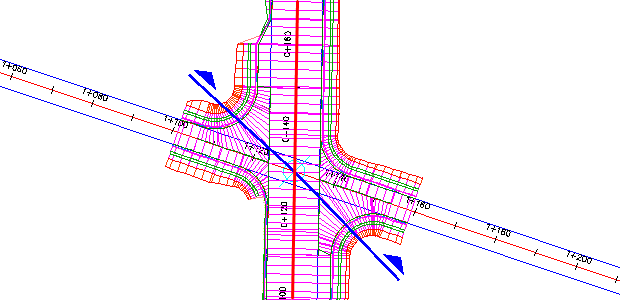
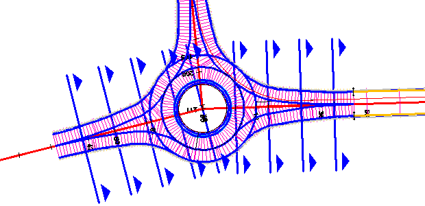
Corridor shapes are used in material volume calculations. When you perform a material quantity analysis, all corridor shapes are used in the calculation.

|
Use a single section to sample multiple baselines or corridors at the same time. |

 00:03:19
 With Audio