Create an alignment that follows the most logical path through a series of feature lines, COGO points, or AutoCAD lines, arcs, points, or blocks.
You can adjust the command to obtain the desired results based on the type and the accuracy of the source data.
For example, when you use COGO points as source data, Autodesk Civil 3D determines the most logical sequence of the COGO points and then reverses the order of any that don't correspond to the sequence of the other selected COGO points.
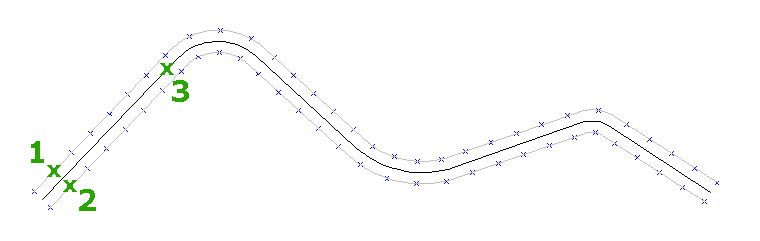
When two paths of roughly parallel COGO points are used, an AutoCAD spline (1, 2) is created through each path of points. The points from each spline are projected onto the other spline; points where the two projections meet are used to create the centerline (3).
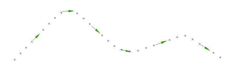
Next, Autodesk Civil 3D calculates curves (1) based on the sequence of the points and the specified Maximum Radius For Curve Detection setting. Autodesk Civil 3D approximates the curvature by linking the sample points together with linear segments. To increase the accuracy when using either feature lines or AutoCAD elements, intermediate sample points may be either weeded from the original input data or created between each pair of sample points. When a sequence of points has a radius that is greater than this setting, the points will form a straight (2). The apparent intersection of the straights (3) are the intersection points for the alignment straights.
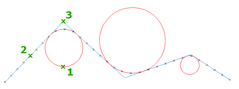
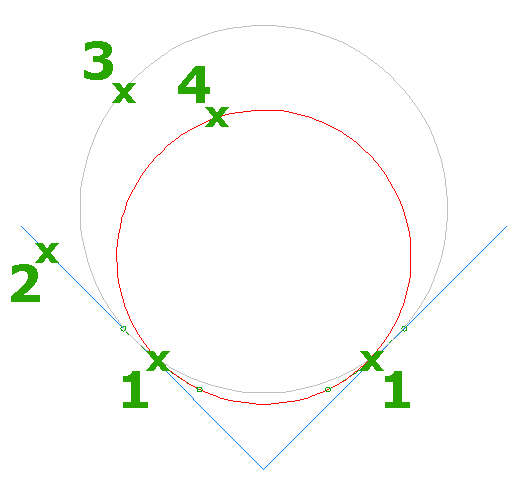
When the Create Transitions option is selected, Autodesk Civil 3D creates a symmetrical pair of transitions (1) between each curve and its tangents. If transitions that meet the specified R/A value do not fit between the straights (2) and the curve (3), then the curve radius is reduced (4) until a solution is found. When you specify this option without the Create Transitions and Match Straights Where Possible option, the transitions will be symmetrical, but the solution may have greater error.
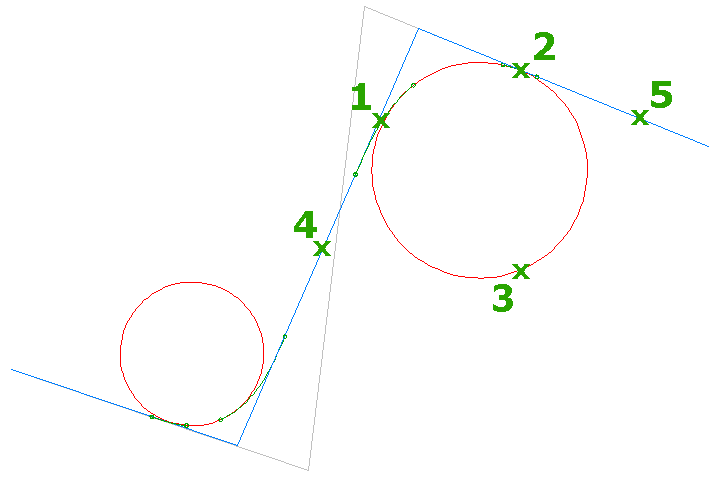
When the Create Transitions and Match Straights Where Possible option is selected, Autodesk Civil 3D creates an asymmetrical pair of transitions (1, 2) between each curve (3) and its straights (4, 5). If a transition that meets the specified minimum R/A ratio does not fit between a curve and a straight, then the straight (4) is moved toward the curve until a solution is found. The minimum R/A value enables you to restrict the transition lengths; a higher value produces shorter transitions, while a lower value produces longer transitions.