Use this tab to transform the coordinate system specified on the Units And Zone tab to local specifications.
- Zone Description
-
Displays the description of the zone that is selected on the Units And Zone tab.
- Apply Transform Settings
-
Specifies whether to apply the settings for coordinate system zone transformation. Selecting this check box enables all the other settings in the dialog box. You cannot select this check box if a zone is not specified on the Units and Zone tab.
Apply Sea Level Scale Factor
Specifies whether to apply the settings for curvature correction to survey data so that measured horizontal distances are reduced to the distances at the mean seal level (geodetic distances).
- Level
-
Specifies the mean level value of your project site with respect to the mean sea level.
- Spheroid Radius
-
Displays the spheroid radius for the spheroid used by the coordinate system. This value is the radius of a spheroid close to the shape of the Earth at sea level, approximately 6,370 km. The value shown in this box is derived from the ellipsoid for the current zone.
Grid Scale Factor
- Computation
-
Specifies the type of scale factor:
- Unity: Uses 1.00 for all points within the zone.
- User Defined: Allows you to specify your own scale factor. For example, you can enter the average scale factor of the points in your survey. This value is used for all points or locations within the zone and is constant.
- Reference Point: Uses the scale factor of the specified reference point as the grid scale factor for all points within the zone.
- Prismoidal Formula: Uses the prismoidal formula to calculate the grid scale factor. This method is recommended because it accounts for the fact that every point has a different scale factor. The following equation is used to calculate prismoidal scale factor.
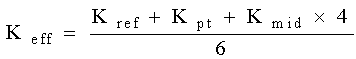
Where:
- Keff is the grid scale factor
- Kref is the scale factor of the reference point
- Kpt is the scale factor of the current point
- Kmid is the scale factor of the midpoint between the reference point and the current point.
A different value is used for each point or locations within the zone.
- Scale Factor
-
Specifies the grid scale factor. Enabled only when you select User Defined for Computation.
Reference Point
Use this section to specify a reference point for transformation. The reference point could be a benchmark that was used in a survey. It can be any point for which you know both the local coordinates and the grid coordinates.
-
 Select Point In Drawing
 -
Click to pick a reference point on the screen.
- Point Number, Local Northing, Local Easting, Grid Northing, Grid Easting
-
Specifies a reference point by its point number, Local Northing and Easting values, or Grid Northing and Easting values.
Rotation Point
Use this section to specify a rotation about the reference point in one of two ways: specify a rotation point, or apply a grid rotation angle.
- Select Point In Drawing
-
Click to pick a rotation point on the screen to set the local Northing and Easting.
- Point Number, Local Northing, Local Easting, Grid Northing, Grid Easting
-
Specifies a rotation point by its point number, Local Northing and Easting values, or Grid Northing and Easting values.
Specify Grid Rotation Angle
Click to apply a rotation angle to grid north and whole circle bearing instead of using a rotation point.
- To North
-
Specifies the rotation angle to north. Enter an angle or click
and pick a point or line in the drawing. The rotation to grid north is the difference between the local coordinate system's north meridian and the grid north meridian of the current zone. If you are using True North, this value may equal the convergence angle. If you are using Magnetic North, this value is derived from the declination angle and the convergence angle.
- Whole Circle Bearing
-
Specifies the direction of the whole circle bearing. Enter an angle or click
and pick a point or line in the drawing. Grid whole circle bearing is the angle between the drawing north and the line defined by reference grid and rotation grid points.