Use this tab to define the appearance of the fitting in a 2D plan view.
Fitting
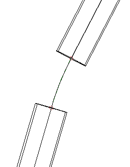
Fittings can be represented in plan view by their centreline, or by a block symbol.
- Display as Centreline
-
Displays the fitting as the centreline of the block that is defined in the pressure network catalogue.
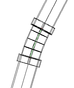
- Display as Catalogue-Defined Block
-
Displays the fitting using the block defined in the pressure network catalogue.
- Display As User-Defined Block
-
Displays the fitting using a user-specified block. The following options are available:
- Block Name: Specifies the name of the block to use as the fitting symbol. You can select a block from the current drawing, or add a block to the drawing by choosing a drawing file. A preview of the block is shown in the panel on the right.
- Customise Block for Vertical Bends: Specifies the name of the block to use to represent vertical bends in plan view. Select the tick box and select a block to use. A preview of the block is shown in the panel on the right.
- Size Options:
- Use Drawing Scale: When this option is selected, the values specified in the X Value and Y Value boxes (inches, or millimetres, when the drawing linear unit is set to Feet or Metres, respectively) are multiplied by the drawing scale to determine the size of the fitting symbol displayed in the drawing. Use this setting when annotation symbols are used.
- Use Fixed Scale: When this option is selected, the Fixed Scale group box is enabled. The fitting symbol will be scaled by the Fixed Scale X, Y and Z parameters.
- Use Size in Absolute Units: When this option is selected, the specified values entered in the X Value and Y Value boxes are absolute values of the drawing linear units (inches, or millimetres, when the drawing linear unit is set to Feet or Metres, respectively).
- Use Size as Percentage of Screen: When this option is selected, the values specified in the X Value and Y Value boxes are percentages of the drawing screen size. The size of the fitting symbol displayed in the drawing is always the same percentage specified as that of the drawing screen size.
- Use Fixed Scale From Part Size: When this option is selected, the Fixed Scale group box is enabled. The fitting symbol will be scaled by the Fixed Scale X, Y and Z parameters based on the object part size.