Use this dialog box to view and change grading-related settings.
This topic documents settings in all grading-related Edit Settings dialog boxes (drawing-level, feature-level, and command-level).
- Drawing-level ambient settings are identified by the
 drawing icon.
- Grading feature settings are listed near the top of this dialog box, after the General property group, and are identified by the
 grading icon.
- Grading command settings are identified by the
 command icon.
The precision and number format display used by all grading commands and used to display grading values is specified in the drawing ambient settings.
For general information about drawing, feature and command settings and their interaction, see About Autodesk Civil 3D Settings.
For information about drawing-level ambient settings, see Ambient Settings Tab (Drawing Settings Dialog Box).
Default Styles
Use these settings to specify the default styles for new feature lines and grading groups.
- Feature Line Style
-
Specifies the default style to apply when creating feature lines. Click in the Value column, and click
 to select a style in the Feature Line Style dialog box.
- Grading Style
-
Specifies the default style to apply when creating grading. Click in the Value column, and click
 to select a style in the Grading Style dialog box.
- Cut Slope Grading Style
-
Specifies the default style to apply when creating cut slope grading. Click in the Value column, and click
to select a style in the Cut Slope Grading Style dialog box.
- Fill Slope Grading Style
-
Specifies the default style to apply when creating fill slope grading. Click in the Value column, and click
to select a style in the Fill Slope Grading Style dialog box.
Default Name Format
Use these settings to specify the default name formats for new feature lines and grading groups. Click in the Value column, and click ![]() to make changes in the Name Template dialog box.
to make changes in the Name Template dialog box.
Feature Line Creation
Feature Line Creation (CreateFeatureLineFromAlign)
Use these settings to specify the default behavior for creating feature lines from alignments.
- Feature Line Name
-
Specifies whether a name is applied to feature lines when created.
- Use Feature Line Style
-
Specifies whether a style is applied to feature lines when created.
- Layer Setting
-
Specifies what layer is applied to feature lines when created. The default is Use the Layer Setting which is from drawing settings.
- Weed Points
-
Specifies whether to open the Weed Vertices dialog box so you can weed the objects when converting to a feature line. Change this value to True to open the Weed Vertices dialog box.
- Create Dynamic Link
-
Specifies whether to create a dynamic link to the alignment. Change this value to False to prevent dynamic link creation.
- Mid-ordinate Distance
-
Specifies the mid-ordinate distance for tessellating curves into short line segments. The default is 0.100.
- Transition Tesselation Factor
-
Specifies the factor for tessellating transitions into short line segments. The default is 0.25.
For more information, see About Creating Feature Lines from Alignments.
Feature Line Creation (CreateFeatureLines)
Use these settings to specify the default behavior for creating feature lines from objects.
- Feature Line Name
-
Specifies whether a name is applied to feature lines when created.
- Use Feature Line Style
-
Specifies whether a style is applied to feature lines when created.
- Layer Setting
-
Specifies what layer is applied to feature lines when created. Use the layer setting (from drawing settings). Use the current layer. Use the selected element layer.
- Erase Existing Elements
-
Specifies whether creation commands erase selected objects when they are converted to feature lines. By default objects are erased. Change this value to False to have objects remain in the drawing.
- Weed Points
-
Specifies whether to open the Weed Vertices dialog box so you can weed the objects when converting to a feature line. Change this value to True to open the Weed Vertices dialog box.
- Assign Levels
-
Specifies whether to open the Assign Levels dialog box.
- Level Source
-
Specifies whether to assign levels from a surface, from selected gradings or to set a fixed level.
- Include Intermediate Level Breaks
-
Specifies whether to include intermediate level breaks when assigning levels from a surface or grading group.
For more information, see About Creating Feature Lines from Objects.
Feature Line Creation (DrawFeatureLine)
Use these settings to specify the default behavior for drawing feature lines.
- Feature Line Name
-
Specifies whether a name is applied to feature lines when created.
- Use Feature Line Style
-
Specifies whether a style is applied to feature lines when created.
- Layer Setting
-
Specifies the default layer setting when feature lines are created.
For more information, see To Draw Straight Segments of Feature Lines.
Grading Creation
Use this setting to specify the default behavior for creating grading.
- Transition Region Length
-
Specifies the default length for transition regions. Enter a length in the Value column or click
 and select a distance in the drawing area. Creation commands prompt for the transition length if you select the start point of a grading to be within or near to an existing grading.
For more information, see To Create Grading from a Footprint.
Grading Group Creation
Use these settings to specify the default behavior for creating grading groups.
- Grading Surface Creation
-
Specifies whether a grading group generates an automatic surface by default.
- Use Group Name
-
Specifies whether the automatic surface is named after the grading group by default.
- Surface Style
-
Specifies the default style for the grading group. Click in the Value column, and click
to select a style in the Surface Style dialog box.
- Surface Tessellation Increment
-
Specifies the default maximum distance along the feature line to add supplemental surface triangle lines for better definition of the grading group surface. Enter a length in the Value column or click
and select a length in the drawing area.
- Surface Cone Tessellation Angle
-
Specifies the default maximum angle between supplemental projection lines on exterior corners. Enter an angle in the Value column or click
and select an angle in the drawing area.
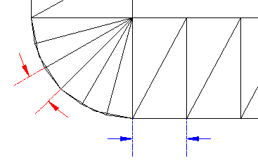
Tessellation settings control the placement of breaklines along rounded exterior corners and straight grading segments
For more information, see To Create a Grading Group.
Feature Line Fit Curve
Use these settings to specify the default behavior for creating feature lines along arcs.
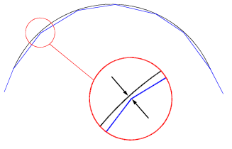
- Tolerance
-
Specifies the maximum distance from an IP along the feature to the arc that is to be inserted. When an arc is inserted, it should pass through all the feature line points (between the start and end points). The tolerance specifies how much any one point can be off of the arc that is averaged through all the points.
Fit Curve Tolerance
- Minimum Number Of Segments
-
Specifies the minimum number of segments that must be identified before creating an arc. This setting is ignored when the Points option is used.
For more information, see About Converting Tessellated Lines to Arcs.
Grading Level Editor
Use these settings to specify the default behavior for the Level Editor, when editing feature lines.
- Raise/Lower Increment
-
Specifies the default vertical distance used for each increment when the feature lines of a grading are raised or lowered to adjust volumes.
- Show Gradient Breaks Only
-
Specifies whether only the feature line start/end points and any gradient breaks in between are displayed. This option simplifies the editing process by allowing level edits to span multiple points.
For more information, see About Editing Feature Lines with the Grading Elevation Editor.
Grading Layout Tools
Use these settings to specify the default criteria for grading layout.
- Grading Criteria Set
-
Specifies the default Criteria Set to use when creating grading. Click in the Value column, and click
to select a criteria set in the Grading Criteria Set dialog box.
- Grading Criteria
-
Specifies the default Criteria to use when creating grading. Click in the Value column, and click
to select criteria in the Grading Criteria dialog box.
For more information, see About Creating Grading.
Grading Volume Tools
Use these settings to specify the default criteria for grading volumes.
- Raise/Lower Level Increment
-
Specifies the default vertical distance used for each increment when the feature lines of a grading are raised or lowered to adjust volumes. Enter an incremental length in the Value column or click
and select a length in the drawing area.
- Limit Feature Selection To Current Group
-
Specifies whether features outside the current grading group can be selected for raising or lowering in the volume calculations.
For more information, see About Displaying and Adjusting Surface Volumes.
Join Features
Use this setting to specify the default tolerance for joining feature lines.
- Tolerance
-
Specifies how close feature lines must be when using the Join command.
Feature Line Weed
Use these settings to specify the default for weeding vertices.
- Apply Angle Factor
-
Specifies whether the Angle factor in the Weed Vertices dialog box is selected by default.
- Angle Factor
-
Specifies the default Angle factor. Enter an angle in the Value column or click
and select an angle in the drawing area.
- Apply Gradient Factor
-
Specifies whether the Gradient factor in the Weed Vertices dialog box is selected by default.
- Gradient Factor
-
Specifies the default Gradient factor. Enter a percentage in the Value column or click
and select a percentage in the drawing area.
- Apply Length Factor
-
Specifies whether the Length factor in the Weed Vertices dialog box is selected by default.
- Length Factor
-
Specifies the default Length factor. Enter a length in the Value column or click
and select a length in the drawing area.
- Close Point Removal
-
Specifies whether the 3D Distance factor in the Weed Vertices dialog box is selected by default.
- Close Point 3D Distance
-
Specifies the default 3D Distance factor. Enter a distance in the Value column or click
and select a distance in the drawing area.
For more information, see About Weeding Feature Line Vertices.